
Views: 0 Author: Site Editor Publish Time: 2026-07-15 Origin: Site


Selecting an incorrect seal for a specific hardware groove inevitably causes improper gland fill. This mechanical mismatch leads to rapid extrusion, accelerated wear, or catastrophic fluid bypass during operation. Equipment designers calculate precise tolerances to maintain high-pressure boundaries. When replacing a failed seal, engineers frequently face a frustrating challenge. Missing documentation and heavily deformed legacy parts often obscure the required specifications. Identifying whether your fluid system requires an AS568 O-Ring, a JIS O-Ring, or a standard Metric O-Ring becomes a guessing game. We will provide a comprehensive technical evaluation framework to differentiate these three core sizing standards. You will learn to understand cross-compatibility limits and navigate complex equipment tolerances safely. Finally, we will show you how to correctly specify and measure replacement seals for accurate procurement.
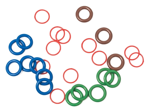
AS568 (Aerospace Standard): The North American standard, categorized by a three-digit "dash number" system, focusing heavily on fractional inch cross-sections (CS).
JIS (Japanese Industrial Standard): The Asian standard (JIS B 2401), uniquely categorized by application-specific prefixes (e.g., P for dynamic, G for static) rather than just dimensions.
Metric (ISO 3601 / DIN 3771): The global standard based purely on exact millimeter measurements (Inner Diameter x Cross-Section), widely used in European equipment.
The Interchangeability Myth: Substituting "close" sizes across standards usually compromises the compression ratio, leading to premature failure in high-pressure or dynamic applications. Measuring the hardware groove is always safer than measuring a used seal.
Imprecise standard matching destroys system integrity rapidly. A cross-section measuring just 0.2mm too small causes significant issues. It drops the required sealing force below acceptable operational thresholds. This sudden drop leads to immediate compression set failure. Fluid bypasses the boundary entirely under pressure. Conversely, an oversized cross-section presents an equally severe threat to your machinery. A seal measuring 0.2mm too large overflows the designated gland volume. Installers inadvertently crush the excess material during assembly. Mechanical nibbling and shearing occur before the equipment even starts.
Maintenance teams often use generic metric kits for quick field repairs. However, using these universal kits to replace specific engineered parts severely hurts reliability. The equipment suffers from drastically reduced Mean Time Between Failures (MTBF). Unplanned downtime skyrockets across the entire production floor. Facilities face repetitive maintenance work orders. Operating generic substitute seals essentially builds future failure points directly into the hardware.
A successful specification requires precise engineering targets based on OEM data. You must achieve optimal gland volume fill to guarantee performance. Industry standards typically demand 70-85% fill rates for general applications. Installers also need appropriate inside diameter stretch for secure seating. Stretching should strictly remain between 1-5% for internal diameters. Engineered tolerances dictate these exact percentages to balance compression and extrusion resistance.
Extrusion: High pressure forces an undersized seal into the hardware clearance gap.
Spiral Failure: Incorrect stretch allows dynamic seals to twist inside the groove.
Explosive Decompression: Improper gland fill traps gases inside the elastomer matrix.
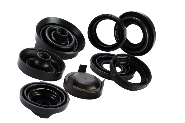
The sealing industry relies on three primary frameworks to govern dimensions globally. Understanding how they function prevents costly procurement errors.
The Society of Automotive Engineers (SAE) promulgated this widely recognized benchmark. Manufacturers categorize the inventory using a standardized dash-number system. Common sizes look like -012 or -214 on spec sheets. These distinct dash numbers map to specific fractional inch dimensions. They also correspond to precise decimal inch measurements for both inner diameter and cross-section. Strengths include highly standardized inventory availability across the continent. You also receive predictable tolerance stacks across US-based manufacturers. Specifying an AS568 O-Ring guarantees structural consistency for domestic hardware.
The Japanese Industrial Standard JIS B 2401 governs this specific standard. It remains absolutely essential for Japanese-manufactured automotive systems. Heavy machinery and robotics also rely heavily on this framework. The categorization logic operates on form-to-function principles. It uses specific letters to dictate the application type before the numerical size.
Class P: Moving or dynamic applications (e.g., piston seals).
Class G: Fixed or static applications (e.g., flange face seals).
Class V: Vacuum environments requiring specialized volumetric fill.
Class S: Special or compact cross-sections for tight spatial constraints.
Ordering a JIS O-Ring requires knowing the operational application beforehand to secure the right prefix.
ISO 3601 primarily governs this extensive global standard. Legacy European systems often reference the older DIN 3771 specification instead. Suppliers express these sizes strictly in exact millimeters. The format always reads Inner Diameter multiplied by Cross-Section. An example reads as 20.00 x 2.50 mm. They do not use sequential dash numbers. This open system allows theoretically infinite size combinations. However, manufacturers maintain standard dimensional tiers to ensure production efficiency. A proper Metric O-Ring fits seamlessly into European equipment designs.
Global Sizing Standards Comparison | |||
Standard Name | Governing Body | Primary Format | Geographic Dominance |
|---|---|---|---|
AS568 | SAE | Dash Number (e.g., -112) | North America |
JIS B 2401 | JSA | Prefix + Number (e.g., P-12) | Japan / Asia |
Metric | ISO / DIN | ID x CS in mm (e.g., 10x2mm) | Europe / Global |
Identifying the correct seal demands a systematic engineering approach. We recommend following a strict evaluation criteria matrix.
Engineers use a first-pass heuristic to identify likely standards. Hardware origin often dictates the underlying seal geometry. North American OEM hardware almost exclusively uses the AS568 system. European machinery defaults to exact metric measurements. Japanese and Korean machinery typically dictates strict JIS requirements. Checking the equipment nameplate provides your first solid clue.
You must evaluate multiple hardware dimensions carefully. Measure the groove width accurately using calibrated micrometers. Assess the groove depth across several different points. Calculate the diametral clearance between mating cylindrical parts. Standard dimensional tolerances differ significantly between geographic regions. The SAE allows for specific inch-based tolerances. These imperial allowances do not translate cleanly to metric groove dimensions. A direct mathematical conversion often yields a non-existent fractional size.
Engineers must account for operational movement during the specification phase. The JIS nomenclature inherently builds this requirement into the part number. The P prefix guarantees a dynamic profile, while G ensures a static fit. Other global standards lack this built-in application indicator. For North American and metric seals, engineers calculate compression ratios manually. You apply different mathematical formulas based on the seal function. Static face seals require different squeeze percentages than dynamic piston seals. Miscalculating this ratio leads to rapid operational failure.

Substituting unverified sizes creates severe operational hazards. Let us examine the most frequent installation mistakes.
Maintenance teams often make a critical field error under pressure. They pull an apparently similar metric seal from a universal repair kit. They use it to replace a failed AS568 or JIS seal. This blind substitution causes unseen mechanical issues. The equipment might hold initial pressure during cold testing. However, dynamic movement quickly exposes the improper gland fill. The "close enough" approach guarantees a secondary failure.
A metric ring might appear physically identical to an imperial dash size. However, the manufacturing tolerances and ± allowances differ greatly. These tiny dimensional discrepancies compound under operating pressure. Thermal expansion also worsens the physical mismatch. As the system heats up, the elastomer expands differently than expected. The final result is a catastrophic bypass leak or sudden blowout.
We must warn against a widespread poor measurement practice. Never use digital calipers on used elastomeric seals. Rubber retains its compression set permanently over time. Heat and fluid exposure cause the material to swell unpredictably. A seal experiencing high pressure extrudes and loses its original circular cross-section. The measured dimensions of a failed seal will actively lie to you.
Maintenance protocols must mandate measuring the metallic hardware instead. Use precision tools to measure the rigid bore diameter. Measure the inner groove diameter and the exact groove width. Use these hard metal dimensions to reverse-engineer the required standard. Metal retains its shape, providing the only reliable baseline for seal specification.
Purchasing the correct seals requires clear communication between engineering and suppliers.
Procurement teams need a structured shortlisting process for vendors. Narrow down the correct supplier based on their actual inventory depth. Look for suppliers stocking specific, documented engineering standards. Avoid suppliers who only sell generic "metric equivalents" for imperial sizes. Equivalent sizes rarely meet tight engineering tolerances. A reliable vendor clearly separates their inventory by recognized standard frameworks.
The Suspected Standard: State whether you need AS568, JIS, or Metric up front.
Precise Hardware Measurements: Provide the bore, groove, and clearance data if the standard remains unknown.
Application Type: Clarify whether the seal operates in a static or dynamic environment.
Material Requirements: Specify the exact elastomer family required for fluid compatibility.
Always detail your specific material requirements clearly. Specify the required Durometer or Shore A hardness explicitly. Call out the elastomer family, such as NBR, FKM, or EPDM. Remember, dimensional standards govern physical size only. They do not dictate chemical material properties or temperature ratings.
Consider industry compliance rules when sourcing standardized rings. Ensure the supplier meets ISO 9001 quality management standards consistently. Specific industries require additional stringent certifications. Food processing machinery needs FDA or NSF material approval. Aviation applications demand strict aerospace compliance documentation and batch traceability. A reputable supplier provides full documentation upon request.
Choosing a sizing standard is never a matter of personal preference. Hardware geometry strictly dictates the required seal dimensions. Mixing standards compromises system integrity immediately, leading to leaks and equipment damage. When in doubt, bypass the deformed elastomer entirely. Measure the metal gland directly to establish true operational requirements. Consult standard dimension charts to verify tolerances against your findings. You can also consult an application engineer to guarantee optimal performance. We encourage you to reach out to your engineering team today. They can provide vital cross-referencing assistance and complete tolerance verification. Request a formal quote for specific standards to ensure reliable, leak-free operations.
A: No. While some sizes are mathematically close, standard tolerances and required gland fill ratios differ, risking extrusion or leakage.
A: They indicate the engineered application: P for dynamic (moving) seals, G for static (fixed) seals, V for vacuum applications, and S for special/smaller cross-sections.
A: The most reliable method is identifying the country of origin of the equipment (US = AS568, Japan = JIS, Europe = Metric) and verifying by measuring the actual metal groove dimensions, not the old O-ring.
A: Dash numbers (like -214) belong exclusively to the AS568 standard. Metric and JIS rings do not use this dash sizing system.


