
Views: 0 Author: Site Editor Publish Time: 2026-11-30 Origin: Site


Rubber gasket compression stops limit how far mating components can close during assembly. When properly designed, they help keep gasket compression within a defined range while providing a separate path for part of the fastener load.
They are worth considering when excessive closure, flexible covers, or assembly variation makes gasket compression difficult to control. However, they do not guarantee sealing, prevent all material aging, or remove the need for correct fastener loading.
The decision should start with the complete joint: gasket profile, dimensional tolerances, flange stiffness, operating conditions, and maintenance requirements.
Table of Contents
As a joint closes, the rubber gasket deforms between its mating surfaces. A compression stop is positioned so that rigid contact occurs at a designed closure distance.
After contact, additional tightening primarily increases load through the stop and surrounding structure. The arrangement reduces further closure, although elastic deformation of the hardware can still change local gasket compression.
The stop must therefore have suitable strength, bearing area, and support. A small spacer pressing into a flexible or weak surface may not maintain the intended gap.
Compression control can be incorporated into the gasket or designed into the hardware.
Arrangement | How it controls closure | Main design consideration |
|---|---|---|
Integral carrier or limiter | A rigid feature within the gasket assembly establishes contact | Relationship between sealing-element height and carrier thickness |
Separate sleeves or spacers | Components between the mating parts define the closed distance | Location, retention, bearing area, and dimensional consistency |
Machined shoulders or bosses | Features on the housing or cover establish the closing position | Machining tolerances and local stiffness |
Groove with mating lands | Surrounding surfaces contact while the gasket remains compressed in its groove | Groove depth, gasket height, and available groove volume |
A washer under a bolt head does not necessarily control the sealing gap. The limiter must act through the relevant load path between the mating components.
Likewise, a sleeve protecting a plastic bolt boss does not automatically establish the correct compression at a nearby gasket.
A rigid stop controls geometry. It does not actively compensate for rubber stress relaxation in the way a suitably designed spring-loading arrangement may.
Even at a controlled gap, the gasket can lose sealing force as its material relaxes or ages. Thermal movement and pressure can also affect the assembly.
Evaluate dimensional control and retained sealing force separately.
Consider stops when inspection shows pinched sections, displaced material, or inconsistent gasket thickness after assembly.
First establish the cause. Incorrect gasket dimensions, unsuitable material, excessive tightening, and poor alignment can produce similar symptoms.
A stop can improve closure control when these factors are understood. It should be part of a defined assembly design rather than an improvised response to recurring leaks.
Thin covers and plastic housings may deform around fasteners before the gasket is compressed evenly.
Properly supported limiters can help protect local bearing areas and control closure. However, fastener spacing, cover stiffness, ribs, and the sealing profile may also need attention.
Stops located only near bolts cannot guarantee a uniform gap between them. The cover may still bend, leaving some areas under-compressed.
Frequently opened covers can benefit from a defined closing position. This can reduce variation between assembly cycles and make installation more consistent.
However, repeated closure to the same position does not prove that the gasket remains reusable. A seal that has taken compression set may receive less compression at that position.
Follow the equipment’s replacement instructions and inspect the gasket, stops, and mating surfaces during maintenance.
Some molded, hollow, foam, or conductive sealing profiles require specific compression conditions.
A suitably designed stop may help keep the profile within its recommended range. The target must come from the actual product’s design guidance and validation.
Low-pressure enclosures can need careful compression control just as pressure-containing joints do. Pressure alone is not a reliable rule for deciding whether stops are necessary.
Stops cannot restore flange flatness, remove corrosion, or correct a misaligned pipe connection.
Adding spacers to a distorted joint may cause early contact at one location while leaving another area insufficiently compressed. Inspect and correct the mating components before changing the sealing arrangement.
Do not use the bolts to force incompatible or badly misaligned parts together.
Compression stops do not eliminate compression set, stress relaxation, chemical swelling, or thermal degradation.
The compound must still suit the operating medium, cleaning chemicals, temperature, and expected service duration.
Lixu Rubber’s rubber gaskets and seals include several material options. Select the specific compound using application requirements and relevant test data.
Some assemblies already achieve suitable compression through their groove geometry, mating lands, stiffness, and fastening procedure.
Adding separate limiters can introduce extra tolerances, loose components, or new load concentrations without improving performance.
Use a stop where it resolves an identified design requirement. Confirm that modifications to an existing joint are approved before installation.
For a simple flat gasket between parallel surfaces:
Compression (%) = (free gasket thickness − assembled sealing gap) ÷ free gasket thickness × 100
The assembled sealing gap is the distance between the surfaces compressing the gasket. It may differ from the physical length of a sleeve or spacer, depending on where that component seats.
For molded beads, hollow profiles, or irregular sections, use the manufacturer’s definition of free height and deflection.
There is no universal compression percentage suitable for every rubber gasket.
Suppose a flat gasket has a free thickness of 4.0 ± 0.2 mm and the assembled sealing gap is 3.0 ± 0.1 mm.
Condition | Calculation | Result |
|---|---|---|
Nominal compression | (4.0 − 3.0) ÷ 4.0 × 100 | 25.0% |
Minimum compression | (3.8 − 3.1) ÷ 3.8 × 100 | 18.4% |
Maximum compression | (4.2 − 2.9) ÷ 4.2 × 100 | 31.0% |
A nominal 25% design therefore produces a much wider range when tolerances are included.
These numbers are illustrative, not recommended limits or Lixu Rubber specifications. Compare the calculated extremes with the approved range for the selected gasket.
Also evaluate flange deflection, stop deformation, temperature effects, and other dimensions contributing to the gap.
Specify the limiter’s load capacity, contact area, support conditions, and resistance to indentation or deformation.
Material selection should account for corrosion, contact with the process medium, operating temperature, and compatibility with adjacent components.
Placement matters as much as height. Review the complete sealing perimeter and the unsupported spans between stops.
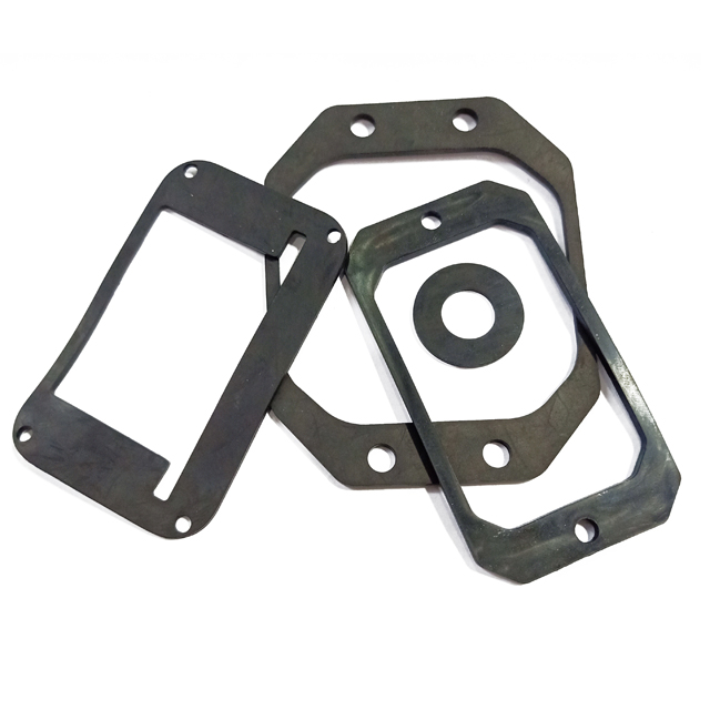
For a custom flat seal, share the full joint drawing when discussing industrial rubber flat gaskets and washers. A gasket outline alone does not show how the joint closes.
Stop contact does not establish that the bolt has reached its required preload.
Continue to specify fastener grade, thread condition, approved lubrication, tightening sequence, and loading method. Excessive tightening can damage bolts, threads, limiters, or housings.
Thread lubrication and gasket-face treatment are separate decisions. Use sealants, adhesives, or assembly lubricants only where the applicable instructions permit them.
Check compression across the sealing path using an appropriate inspection method. Test representative tolerance conditions where necessary.
Validation should address operating pressure, temperature, fluid exposure, vibration, and maintenance cycles relevant to the equipment.
Define acceptance criteria for leakage, hardware deformation, gasket damage, and replacement. Confirm whether limiters are captive or require a separate installation check.
Contact Lixu Rubber with your gasket drawing, joint geometry, operating conditions, and target compression range to discuss the rubber component requirements. Confirm availability separately if an integrated limiter assembly is required.
No. They are useful where closure control addresses a specific problem. An existing groove or validated joint design may already provide suitable compression.
They can reduce excessive deformation caused by assembly closure. They do not eliminate compression set or aging caused by time, temperature, and the service environment.
Yes. Further tightening can overload bolts, threads, stops, or mating components. The specified fastening procedure still applies.
Only if they form part of an engineered load path and meet the required dimensions and strength. A washer beneath a bolt head usually does not directly establish the gasket gap.
No. Reuse depends on the seal design, service history, condition, and equipment instructions. Closure control alone does not establish a permitted reuse cycle.


