
Views: 0 Author: Site Editor Publish Time: 2026-08-08 Origin: Site


Standard O-rings rely heavily on initial mechanical compression to create a functional seal. As system pressure increases, the dynamics of the elastomer change drastically. Miscalculating this shifting relationship often leads to catastrophic blowouts. It also triggers severe safety hazards and causes unexpected equipment failure. You cannot treat extreme environments using standard low-pressure assumptions. High-pressure dynamics force elastomers to behave in entirely different ways.
This article bridges the critical gap between theoretical fluid dynamics and practical engineering decisions. We detail exactly how intense environments dictate your material selection. We also explore proper groove design and rigid dimensional tolerances. Our primary focus is equipping engineers and procurement specialists with strict evaluation criteria. You will learn how to specify resilient solutions, mitigate extrusion risks, and prevent premature seal failure. By understanding contact stress and gland geometry, you can confidently optimize your hardware designs for the most demanding applications.
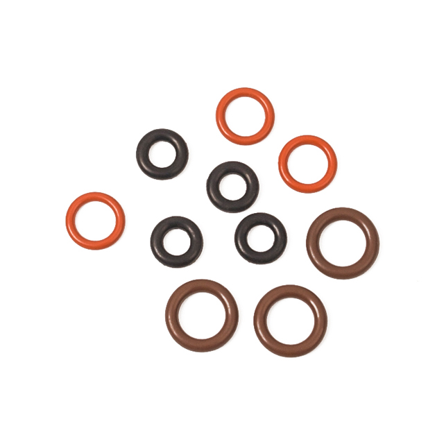
System fluid pressure actively "energizes" the O-ring, increasing contact stress against hardware surfaces to maintain a seal—up to the material's physical limits.
Extrusion and nibbling are the primary failure modes when operating pressures exceed the material hardness and clearance gap threshold.
Upgrading to a High-pressure O-Ring requires balancing higher durometer materials (e.g., 90 Shore A) with tighter machining tolerances or the integration of backup rings.
Optimal sealing performance requires a holistic evaluation of pressure, temperature fluctuations, and chemical compatibility, not just static pressure ratings.
Every reliable sealing system begins with mechanical interference. When you install an elastomer, you compress it between mating hardware surfaces. This initial squeeze handles the low-pressure baseline seal. The rubber pushes back against the metal. This outward force prevents initial fluid bypass. However, static compression only works up to a certain point.
As system fluid enters the gland, the physical mechanics change entirely. High fluid pressure actively shifts the seal toward the low-pressure side of the groove. The elastomer deforms against the hardware walls. This creates a pressure-energized barrier. To stop a leak, the localized contact stress of the elastomer must always exceed the system fluid pressure. Fluid pressure essentially forces the rubber tightly into microscopic surface gaps. The harder the fluid pushes, the tighter the rubber seals against the metal interface.
Engineers must acknowledge strict physical deformation limits. Elastomers are essentially highly viscous, incompressible fluids under extreme force. They cannot absorb volume. They merely shift shape. If pressure pushes them too hard, they will flow into any available clearance. You must design hardware geometries anticipating this exact fluid-like behavior. Without proper boundaries, the rubber simply moves until it breaks. We often see engineers ignore this fluid-like nature. They treat rubber as a solid block. This common mistake leads directly to seal degradation.
Recognizing how seals fail is critical for designing better hardware. High-pressure environments accelerate physical degradation. You must understand these mechanics to prevent premature system failure.
O-Ring Extrusion and Nibbling: This represents the most common high-pressure failure mode. Extrusion occurs when fluid forces the elastomer into the clearance gap between mating metal parts. The rubber literally extrudes like paste into the gap. Nibbling happens next. Repeated pressure cycling pulls and pushes this extruded material. The sharp metal edges "nibble" or tear the rubber away. Over time, the seal loses critical mass and blows out entirely.
Rapid Gas Decompression (RGD): Also known as explosive decompression, RGD plagues high-pressure gas applications. In deep-sea drilling or gas processing, system gas permeates the rubber matrix over time. It sits harmlessly inside the elastomer as long as pressure remains high. When system pressure drops suddenly, this trapped gas expands rapidly. The gas tries to escape but cannot move fast enough. It literally tears the seal from the inside out, causing deep internal ruptures and surface blisters.
Permanent Compression Set: Extreme pressure forces the seal into a highly distorted shape. Prolonged exposure causes mechanical fatigue. When you combine high pressure and high temperatures, the rubber loses its elastic memory. The polymer chains break and reform in the distorted shape. Once system pressure drops, the seal cannot spring back. It loses its ability to maintain contact stress, creating an immediate leak path during the next pressure cycle.
You can identify these failure modes through visual inspection during maintenance teardowns. Extrusion leaves distinct shaved edges. RGD leaves deep pockmarks and internal splits. Compression set leaves the seal looking permanently flattened.
Hardware geometry dictates success just as much as rubber chemistry. You must evaluate your clearance gaps rigorously. Allowable diametral clearance drops exponentially as system pressure rises. A gap perfectly safe at 500 PSI becomes a catastrophic failure point at 3,000 PSI. You must machine hardware tolerances tightly to keep the extrusion gap as small as possible.
When you cannot shrink clearance gaps further, you must use backup rings. Backup rings act as anti-extrusion barriers. They sit behind the elastomer and physically block the clearance gap. When pressure shifts the rubber, it hits the hard backup ring instead of extruding into the void.
Contoured vs. Flat Backup Rings: Flat rings offer a simple, cost-effective barrier. Contoured rings feature a concave face. They physically cup the O-ring, helping preserve its round shape and distributing stress more evenly.
Material Selection (PTFE vs. PEEK): Standard PTFE handles moderate needs efficiently. However, PTFE can cold-flow under extreme loads. For severe hydraulic forces, you need harder materials like PEEK, Nylon, or hard 90-durometer elastomers.
Implementation Logic: Use one backup ring for single-acting pressure systems. Place it strictly on the low-pressure side of the groove. Use two backup rings for double-acting systems, placing one on each side of the seal to handle reversing pressure waves.
Surface finish requirements become absolutely critical here. You need rigid surface finish tolerances (RMS/Ra). High pressure physically forces rubber deep into metal micro-imperfections. Rough surfaces act like abrasive sandpaper. Every time pressure cycles, the rubber shifts slightly against this rough metal. This causes rapid abrasive wear. Smooth surfaces prolong seal life significantly under extreme loads.
Selecting the right compound is a delicate balancing act. You cannot simply default to standard materials when forces escalate. Engineers must carefully evaluate durometer ratings alongside environmental variables.
Standard 70 Shore A materials handle general industrial duties well. They deform easily, filling groove imperfections to create reliable static seals. However, they lack the structural rigidity required for intense forces. High-pressure environments demand 90 Shore A materials. These harder compounds resist extrusion naturally. They maintain their shape under heavy loads.
This upgrade introduces notable trade-offs. Harder materials demand significantly higher clamping forces during installation. They also create much higher friction in dynamic applications, potentially causing heat buildup and premature wear. Furthermore, rigid 90-durometer seals struggle to conform to hardware featuring wide tolerance variations or poor surface finishes.
You must also explore advanced material profiles for specialized environments. Standard Nitrile (Buna-N) often fails when pushed beyond basic hydraulic duty. Polyurethanes offer unmatched extrusion and abrasion resistance for extreme heavy-machinery hydraulics. FKM (Viton™) and HNBR provide exceptional stability combined with broad temperature and chemical resistance. For offshore oil and gas sectors, you must use specialized RGD-resistant compounds. These specific formulations comply with strict NORSOK M-710 standards to survive explosive decompression cycles safely.
Material Type | Typical Durometer | Primary High-Pressure Strength | Common Application Risk / Limitation |
|---|---|---|---|
Standard Nitrile (NBR) | 70 - 90 Shore A | Cost-effective hydraulic sealing. | Poor high-temperature stability; prone to rapid compression set. |
Polyurethane (PU) | 90 - 95 Shore A | Exceptional extrusion and abrasion resistance. | Hydrolytic degradation in hot water or steam environments. |
FKM (Viton™) | 75 - 90 Shore A | High thermal stability and broad chemical resistance. | Poor low-temperature flexibility in extreme cold climates. |
HNBR | 80 - 90 Shore A | Excellent mechanical strength and sour gas resistance. | Higher procurement costs compared to standard NBR. |
Review this data carefully before finalizing your procurement sheets. Matching the exact compound to your specific fluid and temperature profile prevents costly field replacements.

Applying the correct squeeze is fundamental to establishing your initial baseline seal. Squeeze defines how much the hardware compresses the rubber cross-section. Baseline squeeze limits differ strictly by application type. Static applications generally require 15% to 30% squeeze. The rubber does not move, so you can compress it heavily. Dynamic applications need much tighter control. They usually demand 8% to 16% squeeze to minimize friction and prevent accelerated wear.
Engineers often face the high-pressure squeeze dilemma. Many technicians mistakenly over-squeeze seals to compensate for high system pressure. This represents a dangerous practice. Excessive squeeze severely accelerates permanent compression set. It also causes mechanical shear during hardware assembly. The rubber physically fractures before the machine ever turns on.
Conversely, under-squeezing is equally dangerous. If you do not compress the rubber enough, fluid bypasses the seal entirely. The leak occurs before system pressure can shift and energize the elastomer against the groove wall. You must strike a precise mathematical balance based on cross-section tolerances.
We strongly recommend utilizing Finite Element Analysis (FEA) for critical applications. FEA modeling allows engineering teams to simulate fluid dynamics digitally. It predicts contact stress distribution across the elastomer profile. It also maps out precise extrusion risks long before you machine expensive metal hardware. FEA ensures your tolerance stack-ups perfectly align with your chosen durometer.
Application Type | Recommended Squeeze Ratio | Primary Design Goal |
|---|---|---|
Static (Face Seal) | 15% - 30% | Maximum contact stress; tolerate surface imperfections. |
Static (Radial Seal) | 10% - 25% | Reliable fluid barrier; manageable installation force. |
Dynamic (Reciprocating) | 8% - 16% | Minimize friction; prevent spiral failure and heat buildup. |
Dynamic (Rotary) | 2% - 8% | Extreme friction reduction; prevent elastomer melting. |
Securing ultimate sealing performance under extreme force is rarely about simply finding stronger rubber. It requires a highly coordinated engineering approach. You must perfectly align your material durometer, groove geometry, and precise gap tolerances. Ignoring any single variable invites catastrophic extrusion or explosive decompression.
When specifying a High-pressure O-Ring, always apply disciplined shortlisting logic. First, audit your current clearance gaps rigorously. Second, map out your operating temperature fluctuations. Heat severely softens elastomers, turning a reliable 90-durometer seal into a vulnerable component. Never hastily switch to a harder compound without confirming your hardware tolerances can handle the increased installation forces.
We encourage you to take proactive steps today. Submit your precise gland dimensions, fluid pressure parameters, and environmental variables to our engineering team. We will help you specify custom material compounds and optimal backup ring configurations. Let us engineer a robust, long-lasting solution tailored exactly to your most demanding industrial applications.
A: A standard 70-durometer O-ring generally handles up to 1,500 PSI (100 bar). However, this assumes strict, factory-standard clearance gaps and moderate room temperatures. If your hardware features large clearance gaps or operates at high temperatures, this pressure threshold drops significantly. Always verify gap dimensions before omitting backup rings.
A: High temperatures aggressively soften elastomers. This thermal softening lowers their effective durometer rating. An O-ring that easily survives 3,000 PSI at room temperature may extrude and fail at 1,500 PSI if the system runs hot. You must account for thermal degradation during the material selection process.
A: Rarely. If the leak stems from high-pressure extrusion or insufficient material hardness, increasing the initial squeeze only worsens the problem. It accelerates material degradation and compression set. To solve high-pressure leaks, you usually need to reduce clearance gaps or install rigid backup rings.
A: Not always. High-durometer O-rings are very stiff and require significant mechanical force to compress properly. In low-pressure systems, there may not be enough fluid pressure to fully energize a hard elastomer against the groove. This lack of contact stress often leads to weeping or persistent slow leaks.


