
Views: 0 Author: Site Editor Publish Time: 2026-08-24 Origin: Site


A failed seal often carries a disproportionate operational burden. A single component costing mere cents can trigger thousands of dollars in unplanned downtime, hazardous fluid loss, and severe safety risks on the plant floor. Engineers frequently face a frustrating gap between theoretical seal design and real-world operational variables. Recurring leaks rarely stem from a simple bad batch of elastomers. Instead, they usually indicate systemic flaws in gland design, material specification, or installation protocols. Solving these issues requires moving beyond quick fixes and reactive maintenance. We must adopt a systematic, engineering-led approach to optimize O-Ring performance across all fluid power and containment systems. By focusing on precise gland design optimization, rigorous material selection, and strict installation procedures, you can eliminate the root causes of failure. This guide breaks down advanced sealing tips to help you build highly reliable systems that withstand harsh industrial environments.
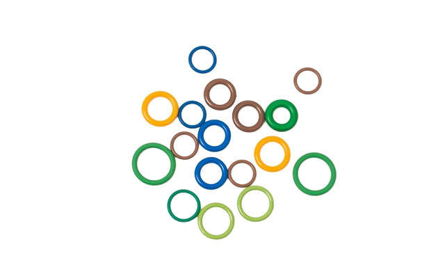
Gland Design Dictates Success: Maintaining optimal compression ratios (typically 10%–30%) based on static versus dynamic application requirements is non-negotiable for long-term reliability.
Surface Preparation Prevents Failure: Eliminating burrs, managing sharp edges, and achieving specific surface finishes through precision machining prevents premature abrasion and nibbling.
Lubrication Requires Precision: Over-lubrication can impede an O-ring from seating properly in the groove and cause bypass leaks, while under-lubrication increases friction and installation damage.
Holistic Material Specification: Selecting the right elastomer requires evaluating the total operating environment—including chemical exposure, pressure cycling, and temperature extremes—rather than relying solely on baseline spec sheets.
Table of Contents
Define what makes a seal successful in high-stakes environments before you finalize any hardware drawings. Success goes beyond simply holding fluid during a five-minute factory pressure test. You need to establish concrete baseline metrics to evaluate long-term effectiveness under actual working conditions. These metrics include acceptable leak rates under maximum pressure, expected mean time between failures (MTBF), and maintenance lifecycle expectations. A reliable seal maintains its structural integrity under fluctuating pressures and extreme temperatures without requiring premature replacement. Tracking these specific metrics helps you identify when a seal begins to underperform long before a catastrophic blowout occurs. Engineers must also consider pressure decay rates and vacuum retention capabilities as part of their baseline testing. By establishing these parameters early, you create a clear standard for evaluating different elastomer compounds and groove dimensions.
Application Type | Media Being Sealed | Acceptable Leak Rate Standard | Primary Performance Metric |
|---|---|---|---|
Heavy Hydraulics | Petroleum-based Oils | Zero visible drops per 1000 cycles | Volumetric retention under pressure spikes |
Pneumatic Cylinders | Compressed Air | < 0.1 psi drop over 24 hours | Low breakout friction and pressure decay |
Chemical Processing | Aggressive Solvents | Zero fugitive emissions (PPM level) | Chemical resistance and volume swell limits |
High Vacuum Systems | Gas/Air | < 1x10^-9 atm cc/sec helium | Outgassing rates and permeation resistance |
Visual inspection provides the physical evidence needed to diagnose poor performance accurately. When you remove a failed seal from a system, examine its condition closely under good lighting. Extrusion appears as a chewed, chipped, or frayed edge on the low-pressure side of the elastomer. This specific damage usually points to excessive clearance gaps or system pressure exceeding the material's yield strength. Nibbling looks similar to extrusion but often results from rapid pressure cycling that pinches the rubber repeatedly. Compression set leaves the O-ring with flat, permanently deformed surfaces. This means the material lost its elasticity due to extreme heat exposure or over-compression within the gland. Spiral failure shows deep, diagonal cuts spiraling around the entire circumference of the elastomer. This is typically caused by twisting during installation or uneven friction during dynamic operation.
Isolate the failed component and lock out the system pressure to ensure safe removal.
Extract the damaged seal using brass or plastic picks to avoid scratching the metal gland surfaces.
Clean the extracted elastomer gently with a compatible solvent to remove heavy grease and debris.
Inspect the cross-section under 10x magnification to identify micro-tears, extrusion frays, or chemical blistering.
Measure the remaining cross-section with digital calipers to calculate the exact percentage of compression set.
Document the physical damage patterns and map them directly to the operating conditions at the time of failure.
Different mechanical applications require highly specific gland configurations. Radial seals operate on pistons or rods, compressing the elastomer between an inner and outer cylinder wall. Face seals sit in a machined flange, compressing the O-ring axially against a flat, rigid mating surface. Specialized designs like dovetail grooves hold the seal securely in place during rapid opening and closing cycles, preventing the rubber from being pulled out by suction. Crush seals deform the elastomer into a tight triangular space, creating a permanent, highly robust barrier. Your choice of gland type dictates the direction of system pressure and establishes the required hardware tolerances for the entire assembly. Selecting the wrong gland architecture guarantees premature failure, regardless of the elastomer quality.
Gland Configuration | Primary Application | Direction of Compression | Design Considerations |
|---|---|---|---|
Radial (Rod/Piston) | Hydraulic cylinders, valve stems | Radial (Inside/Outside Diameter) | Requires strict control of diametral clearance gaps to prevent extrusion. |
Axial (Face Seal) | Pipe flanges, cover plates | Axial (Top/Bottom) | Must account for internal vs. external pressure to position the groove correctly. |
Dovetail Groove | Vacuum chambers, dispensing valves | Axial with mechanical retention | Difficult to machine; requires precise volume calculations to avoid overfilling. |
Crush Seal | Permanent static enclosures | Multi-directional deformation | Single-use only; requires high clamping force to deform the elastomer fully. |
Compression is the fundamental driving force behind a tight, reliable seal. The standard engineering rule of thumb targets a compression ratio between 10% and 30%. You must balance this ratio carefully based on the application. Too little compression leads directly to low-pressure leaks because the elastomer cannot deform enough to fill the microscopic voids in the metal mating surface. Too much compression causes premature compression set, accelerates material degradation, and dramatically increases friction. Static applications, such as pipe flanges and cover plates, can tolerate higher compression, often operating near 25% to 30%. Dynamic applications involving reciprocating rods or rotary shafts require much lower compression, typically 10% to 15%. This lower ratio minimizes running friction, reduces heat generation, and prevents excessive wear on the rubber.
Inside Diameter (ID) stretch directly impacts the cross-section of the elastomer. When you stretch an O-ring over a shaft or piston, its cross-sectional diameter shrinks proportionately. You must account for this physical reduction during the initial design phase to ensure adequate sealing force. Never exceed a 5% stretch at installation for standard applications. Excessive stretch thins the cross-section too much, which drastically reduces the effective compression ratio within the groove. This compromises overall reliability and creates an easy pathway for fluid bypass. Furthermore, excessive stretch places the elastomer under constant internal tensile stress. This stress accelerates chemical attack and makes the material far more susceptible to environmental cracking and premature aging. If your design requires stretching the seal beyond 5%, you must recalculate the groove depth to accommodate the reduced cross-section.
System pressure constantly forces the elastomer toward the low-pressure side of the gland. The maximum allowable extrusion gap depends heavily on the system operating pressure and the elastomer's durometer, or hardness rating. Softer materials will easily extrude through much smaller gaps at relatively low pressures. Harder materials resist this extrusion force far better. When you operate high-pressure fluid systems and cannot tighten the machining tolerances of the hardware any further, you must introduce back-up rings. These hard plastic, PTFE, or PEEK rings sit directly behind the O-ring in the groove. They physically block the clearance gap, preventing the softer elastomer from extruding and tearing under high-pressure spikes. For double-acting cylinders where pressure reverses, you must install back-up rings on both sides of the seal.
System Pressure (PSI) | 70 Durometer (Shore A) Max Gap | 80 Durometer (Shore A) Max Gap | 90 Durometer (Shore A) Max Gap |
|---|---|---|---|
Up to 1,000 PSI | 0.008 inches | 0.012 inches | 0.016 inches |
1,000 to 2,000 PSI | 0.003 inches | 0.006 inches | 0.010 inches |
2,000 to 3,000 PSI | Not Recommended | 0.002 inches | 0.006 inches |
Over 3,000 PSI | Requires Back-up Ring | Requires Back-up Ring | 0.002 inches or Back-up Ring |
The microscopic texture of your hardware directly affects seal longevity and performance. Precision holes created by drilling, boring, and reaming impact the mating surfaces significantly. Rough metal surfaces act exactly like sandpaper, rapidly abrading the elastomer during dynamic cycling or high-frequency pressure pulses. You must rigorously remove all burrs, sharp edges, and machining marks during the manufacturing process. Smooth, properly polished surfaces prevent micro-tears in the elastomer during operation. Engineers typically specify surface finishes between 16 and 32 micro-inches (Ra) for dynamic seals, while static seals can tolerate slightly rougher finishes between 32 and 63 micro-inches (Ra). Achieving these specific finishes ensures the seal remains intact over thousands of operational cycles without wearing down the rubber prematurely.
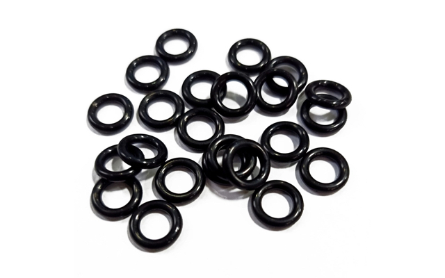
System fluids interact very differently with various elastomer compounds. You must evaluate precisely how your specific media affects materials like standard Nitrile, high-temperature Viton, or flexible Silicone. A slight volume swell can sometimes aid sealing by increasing the effective compression within the groove. However, excessive swell softens the material dangerously, leading to rapid extrusion, loss of tensile strength, and complete mechanical breakdown. Always cross-reference your system fluids with detailed chemical compatibility charts. Pay close attention to chemical concentrations, fluid additives, and exposure durations. A material that survives brief contact with a solvent might degrade completely under continuous immersion. You must also account for outgassing in vacuum applications, where incompatible materials release volatile compounds that contaminate the entire system.
Temperature extremes destroy incorrect materials rapidly. Evaluate elastomers for their continuous operating temperatures rather than just their ability to survive intermittent peak temperatures. Continuous high heat accelerates compression set, bakes the plasticizers out of the rubber, and hardens the material until it cracks. Conversely, cold-temperature embrittlement causes a sudden, catastrophic loss of elasticity. When the material drops below its glass transition temperature (Tg), it freezes and becomes entirely rigid. It can no longer track the microscopic variations in the mating surfaces, resulting in immediate seal failure upon system startup. You must select a compound engineered specifically for your exact thermal operating window. For extreme cold, specialized silicone or low-temperature nitrile compounds provide the necessary flexibility to maintain a seal.
High-performance elastomers like Perfluoroelastomer (FFKM) carry different operational expectations compared to standard commodity rubber. You justify the specification of advanced materials by calculating the total lifecycle value of the component in the field. Look closely at the reduction in required maintenance intervals and the prevention of highly disruptive unplanned downtime. A standard seal that fails every three months forces your maintenance team to halt production, drain fluids, and disassemble heavy machinery repeatedly. A premium seal engineered for harsh chemical and thermal environments can last three uninterrupted years under the exact same conditions. Prioritize long-term operational stability and system reliability over initial component selection. Extending the mean time between failures directly increases your facility's overall production capacity and operational efficiency.
Lubrication is a critical, often overlooked component of successful seal assembly. Select a lubricant that remains entirely chemically compatible with both the O-ring material and the system media. Incompatible grease can rapidly degrade the elastomer or contaminate the fluid line, causing downstream failures. Proper lubrication manages breakout friction during initial movement and significantly reduces running friction in dynamic applications. However, you must actively avoid over-greasing the assembly. Excessive grease prevents the O-ring from moving naturally within the groove to seal the extrusion gap under pressure. This trapped grease can create a physical channel across the sealing line, causing immediate bypass leaks. Apply only a thin, uniform film of lubricant that barely leaves a sheen on the rubber.
Assembly lines and maintenance shops are prime locations for accidental seal damage. Implement strict, documented handling protocols to protect the elastomer during installation. Use specialized installation cones or Mylar sleeves to guide the O-ring safely over threaded shafts, sharp splines, or retaining ring grooves. Avoid stretching the O-ring beyond its elastic limit during manual assembly, as this causes permanent deformation. Prevent twisting at all costs. A twisted O-ring will almost certainly suffer spiral failure once exposed to dynamic motion or pressure cycling. Training your assembly technicians on these specific handling techniques drastically reduces early-life seal failures.
Verify the O-ring dimensions and material compound against the engineering drawing before beginning assembly.
Inspect all metal hardware for burrs, sharp edges, and leftover machining debris.
Apply a micro-thin layer of compatible lubricant to both the O-ring and the mating hardware surfaces.
Slide the O-ring over the shaft using a smooth installation cone to bypass any threads or splines.
Seat the O-ring into the groove using uniform pressure, ensuring it does not roll or twist during placement.
Conduct a visual inspection to confirm the seal sits evenly in the gland without any visible pinching.
Contamination ruins seals before they even begin operating. Emphasize the critical, non-negotiable step of cleaning all mating surfaces thoroughly. Remove foreign particles, airborne dust, and abrasive machining debris before seating the seal in the gland. Even a microscopic metal shaving or a single grain of sand trapped between the elastomer and the hardware creates a permanent leak path. Maintain a clean assembly environment, utilizing lint-free wipes and appropriate solvent cleaners. For highly critical applications, such as aerospace hydraulics or semiconductor manufacturing, perform seal assembly in a dedicated cleanroom environment that meets strict ISO cleanliness standards to ensure the seal performs exactly as engineered.
Theoretical design assumptions always require real-world validation. Advise your engineering team to test seals rigorously in simulated environmental conditions before full-scale deployment. Prototyping reveals unexpected, complex interactions between system pressure, temperature fluctuations, and fluid dynamics. Subjecting the seal to accelerated life testing helps uncover potential weaknesses in the gland design or the chosen material compound. Use Finite Element Analysis (FEA) software during the design phase to model how the elastomer will deform under pressure, but always follow up with physical bench testing. This testing phase allows you to iterate and refine the design before committing to mass production, ultimately preventing field failures and product recalls.
The industrial market contains many counterfeit or out-of-tolerance O-rings. These substandard components introduce massive, unacceptable risk to your operations. Implement robust strategies for verifying dimensional tolerances immediately upon receipt of the components. Check batch consistency regularly using optical measurement tools and verify material hardness using a Shore A durometer gauge. Demand comprehensive material certifications and test reports from your manufacturing partners to ensure the elastomer meets the exact specifications you ordered. Partnering with reputable, established suppliers eliminates the guesswork from your supply chain and guarantees consistent component quality across multiple production runs.
Many application sectors require strict regulatory compliance for all sealing components. Ensure your selected seals meet the necessary industry certifications before installation. Food and beverage applications often demand FDA-compliant materials that will not leach toxins or alter the taste of the product. Medical devices and pharmaceutical processing equipment require USP Class VI certification for biocompatibility and sterilization resistance. Oil and gas operations frequently mandate NORSOK-approved compounds capable of withstanding explosive decompression in high-pressure environments. Verifying these specific standards upfront prevents severe legal complications and operational hurdles down the line.
Audit your current failure modes by cataloging removed seals and identifying physical damage patterns like extrusion or compression set.
Consult with a sealing application engineer to review and adjust your existing groove dimensions, hardware tolerances, and surface finish specifications.
Request material samples from your supplier to conduct internal accelerated life testing under your exact real-world fluid and temperature conditions.
Update your standard operating procedures for assembly to include strict lubrication limits and the mandatory use of installation cones.
Improving O-Ring performance requires a complete approach that combines accurate gland design, compatible elastomer selection, controlled compression, proper surface preparation, and consistent installation practices. Addressing these factors together helps reduce recurring leaks, premature seal failures, and unnecessary maintenance while improving long-term sealing reliability. Cixi Lixu Rubber Products Co., Ltd specializes in rubber sealing products and O-Ring solutions, supporting industrial applications with a focus on reliable sealing performance, material selection, and product quality for diverse operating environments.
A: The ideal compression ratio typically falls between 10% and 30%. Static applications, such as face seals, require higher compression (20% to 30%) to ensure a tight seal. Dynamic applications, involving moving parts, need lower compression (10% to 15%) to minimize friction and prevent premature wear.
A: The most common gland types include radial, face, and dovetail glands. Radial glands compress the seal between inner and outer cylinders. Face glands compress the seal axially against a flat surface. Dovetail glands feature a specialized undercut design to hold the O-ring securely during dynamic opening and closing cycles.
A: Yes, over-lubrication is a frequent cause of leaks. Excessive grease prevents the O-ring from moving naturally within the groove to seal the extrusion gap under pressure. The trapped lubricant can also create a physical channel across the sealing line, leading directly to bypass leaks.
A: Surface finish dictates seal longevity. Rough surfaces cause severe abrasion and micro-tears in the elastomer during pressure cycling. Conversely, overly smooth surfaces may fail to retain the necessary lubrication, increasing friction. Engineers must specify precise machining finishes to balance smooth operation with adequate lubricant retention.
A: Extrusion occurs when high system pressure forces the elastomer into the clearance gap between mating hardware. The primary causes include excessive clearance gaps, extreme pressure spikes, and using an elastomer with insufficient hardness. Installing back-up rings or tightening hardware tolerances prevents this failure.
A: Prevent compression set by selecting elastomers with high temperature resistance suited for your operating environment. Avoid over-compressing the O-ring in the gland design. Ensure the material can withstand continuous operating temperatures without losing its elasticity and flattening out permanently.
A: Static gland designs involve stationary mating surfaces and tolerate higher compression ratios to maximize sealing force. Dynamic gland designs involve moving parts, such as reciprocating rods. They require lower compression ratios and stricter surface finish tolerances to manage friction, reduce wear, and prevent seal degradation.


