
Views: 0 Author: Site Editor Publish Time: 2026-07-23 Origin: Site


Minor dimensional miscalculations in seal design routinely lead to catastrophic leaks, equipment downtime, and severe safety hazards. Operational consequences of seal failure can shut down an entire production line, making precision at the design stage an absolute requirement. Selecting an elastomer based on visual approximation rather than calculating precise mechanical interactions against hardware dimensions is a common engineering pitfall. You cannot simply guess the squeeze, stretch, and gland fill and expect a seal to hold under pressure. This approach guarantees premature failure and extensive rework.
Matching seal dimensions to groove specifications requires a systematic, evidence-based framework. By calculating the exact mechanical interactions between the elastomer and the machined hardware, engineers ensure long-term reliability in both static and dynamic applications. This methodology replaces guesswork with hard data, allowing you to design glands that perform consistently under varying pressures and temperatures.
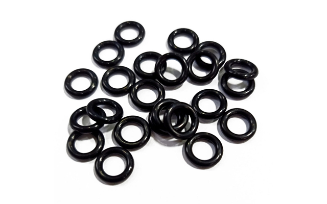
Target Squeeze is Non-Negotiable: Static applications typically require 15-30% squeeze, while dynamic applications require 10-20% to balance sealing force with friction.
The Gland Fill Rule: A properly designed groove must be filled to roughly 60-85% of its volume by the O-ring to accommodate thermal expansion and fluid swell without extruding.
Stretch Limits: An O-ring's Inside Diameter (ID) should generally be stretched no more than 5% during installation to prevent cross-section reduction and premature degradation.
Hardware Tolerances Matter: Factoring in machining tolerances and clearance gaps is critical to preventing O-ring extrusion under high pressure.
Table of Contents
A perfect fit achieves zero leakage, acceptable friction, resistance to extrusion, and longevity under operational pressures. Hitting these success criteria requires a deep understanding of how the elastomer interacts with its machined housing. You must account for the physical deformation of the rubber, the space it occupies, and how it responds to system pressure.
The mathematical relationship between the cross-section and the depth of the hardware groove dictates performance. Gland depth directly controls the compression of the elastomeric material. If the gland is too deep, the seal lacks sufficient squeeze to prevent fluid bypass. If it is too shallow, the elastomer over-compresses, leading to structural damage, compression set, and accelerated wear.
When you machine a groove, the depth must be calculated based on the maximum and minimum cross-section tolerances of the seal. A standard 0.139-inch cross-section might vary by ±0.004 inches. Your gland depth must accommodate this variance while maintaining the required compression percentage. Failure to account for these tolerances results in inconsistent sealing performance across production batches.
Squeeze refers to the deformation of the cross-section when installed in the gland, creating the initial sealing line of contact. Static applications, such as flanges and covers, generally require a higher squeeze to ensure a robust seal, as friction is not a concern. Dynamic applications, including pistons and rods, demand a delicate balance. You need enough squeeze to seal the fluid, but not so much that running friction causes premature wear or stick-slip issues.
Application Type | Recommended Squeeze | Primary Considerations |
|---|---|---|
Static (Face Seal) | 15% - 30% | Maximum sealing force, no friction concerns, high pressure retention. |
Static (Radial) | 15% - 25% | Requires careful installation to avoid shearing the seal on hardware edges. |
Dynamic (Reciprocating) | 10% - 20% | Balance between sealing integrity and running friction. Wear resistance is key. |
Dynamic (Rotary) | 2% - 5% | High heat generation requires minimal squeeze to prevent elastomer degradation. |
Applying a 25% squeeze to a reciprocating piston seal will generate excessive heat, degrade the elastomer, and stall the cylinder. Conversely, applying a 10% squeeze to a high-pressure static flange will likely result in a blowout. Match the squeeze to the specific mechanical demands of the assembly.
A groove must never be 100% filled. Elastomers act like highly viscous incompressible fluids. If they have no room to expand due to thermal changes or fluid swell, they will rupture the hardware or extrude through clearance gaps. Calculating gland volume versus seal volume ensures you hit the 60-85% target. This void space accommodates volumetric expansion without compromising the assembly.
To calculate gland fill, determine the maximum possible volume of the seal (using the upper tolerance limit of the cross-section and inside diameter) and divide it by the minimum possible volume of the groove (using the lower tolerance limits of the groove width and depth). If this number exceeds 85%, widen the groove. Do not increase the depth, as this will alter your squeeze.
Groove sizing calculations differ when specifying alternative sealing profiles like X-Rings (quad-rings) and square cut rings. X-Rings offer localized friction benefits and resist spiraling in dynamic applications. They feature four lobes that create multiple sealing lines, allowing for lower overall squeeze while maintaining fluid retention. Square rings provide high-pressure stability within standard AS568 groove configurations, resisting extrusion better than round profiles.
When retrofitting an X-Ring into a standard groove, verify that the groove width accommodates the slightly wider footprint of the lobed design under compression. Square rings require tighter control over groove corner radii to prevent the sharp edges of the seal from folding or binding during installation.
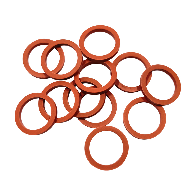
Maintenance engineers often work with pre-machined hardware where groove dimensions are fixed. A replicable framework ensures accurate retrofitting when you need to replace a failed seal but lack the original engineering drawings. Using a comprehensive O-Ring size guide,groove fit methodology prevents repeat failures.
Identify critical measurements: bore diameter, groove diameter, groove width, and diametrical clearance. Use precise measurement tools like calibrated calipers and micrometers. Always account for hardware wear. Worn cylinder walls or scored rods alter the effective clearance gap, significantly increasing extrusion risk under pressure.
Take multiple measurements around the circumference of the groove to check for out-of-roundness or uneven wear. If the diametrical clearance exceeds the allowable limits for the system pressure and elastomer hardness, you must either replace the hardware or specify a seal with backup rings to bridge the gap.
Determine the ideal cross-section based on the measured gland depth and the target squeeze percentage. Use the formula: CS = Gland Depth / (1 - Target Squeeze). Once calculated, select the nearest standard AS568 cross-section to ensure availability.
For example, if your measured gland depth is 0.115 inches and you need a 20% squeeze for a dynamic application, the calculation is 0.115 / (1 - 0.20) = 0.143 inches. The closest standard AS568 cross-section is 0.139 inches. Recalculate the actual squeeze using the 0.139-inch cross-section to verify it falls within the acceptable 10-20% range.
Calculate the required inside diameter based on the groove diameter. For rod and piston seals, apply the 1-5% stretch rule to ensure a snug fit without excessive tension. Excessive stretch reduces the cross-section, lowering the effective squeeze and leading to leakage.
For face seals, the friction-fit requirements dictate that the diameter should be slightly larger or smaller than the groove, depending on whether the pressure is internal or external. If the pressure is internal, size the seal so its outside diameter contacts the outer wall of the groove. If the pressure is external, size the inside diameter to contact the inner wall of the groove. This prevents the seal from shifting when pressure is applied.
When designing hardware around a seal, both the elastomer and groove dimensions are open variables. A chronological sequence ensures optimal performance and manufacturability. You must design the metal around the rubber, not the other way around.
Larger cross-sections are preferred for tolerance handling, gas permeability reduction, and compression set resistance. A larger mass of rubber absorbs machining variations more effectively than a smaller one. Smaller cross-sections save space and weight but demand tighter machining tolerances to maintain consistent squeeze.
If your manufacturing facility struggles to hold tight tolerances on large diameter parts, specify a larger cross-section seal. A 0.275-inch cross-section can absorb a ±0.005-inch machining variance easily, whereas a 0.070-inch cross-section will experience massive fluctuations in squeeze percentage with the same machining variance.
Establish a gland depth that ensures optimal elastomer compression under all tolerance stack-up scenarios. Calculate the maximum and minimum possible gland depths based on machining tolerances to verify that the squeeze remains within the acceptable range.
Determine the maximum seal cross-section (Nominal + Tolerance).
Determine the minimum gland depth (Nominal - Tolerance).
Calculate maximum squeeze: (Max CS - Min Gland Depth) / Max CS.
Determine the minimum seal cross-section (Nominal - Tolerance).
Determine the maximum gland depth (Nominal + Tolerance).
Calculate minimum squeeze: (Min CS - Max Gland Depth) / Min CS.
Adjust your nominal gland depth and machining tolerances until both the maximum and minimum squeeze values fall within your target range.
Size the groove width to leave adequate void space for material expansion, volume swell, and thermal expansion. Ensure the maximum elastomer volume does not exceed 85% of the minimum gland volume under worst-case tolerance conditions.
When dealing with aggressive fluids that cause high volume swell, you may need to target a 60% nominal gland fill to leave enough room for the rubber to expand. Always consult the material data sheet for the specific elastomer compound to determine expected swell percentages in the system fluid.
Prototyping and test-rig assembly present unique challenges when designers have a free choice of both groove and seal dimensions. Prioritize standard AS568 sizes to minimize tooling lead times. Design the groove around readily available seals rather than specifying custom sizes that delay project timelines.
Using standard sizes allows you to quickly test different elastomer compounds (Nitrile, Viton, EPDM) without waiting for custom molds. Once the prototype is validated, you can optimize the hardware for production, knowing the standard seal geometry works.
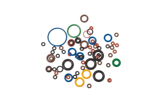
Hardware design choices directly impact seal performance and operational outcomes. The geometry of the groove must match the specific function of the joint.
Distinct groove geometry requirements exist for each seal type. Pressure direction dictates whether the elastomer should sit against the outside or inside wall of the groove. Piston seals sit in a groove machined into the piston and seal against the cylinder bore. Rod seals sit in a groove machined into the housing and seal against the moving rod.
Square face grooves offer different sealing characteristics and gland constraints compared to round face grooves. Assembly retention mechanics, such as undercut (dovetail) grooves, utilize friction to keep seals in place during assembly. Dovetail grooves are notoriously difficult to machine and require precise calculations to ensure the seal can be installed without tearing while still providing adequate retention.
For large-diameter face seal applications, custom spliced and vulcanized seals require specific tolerance considerations. The splice joint is often slightly larger or smaller than the rest of the cord stock, meaning the groove must accommodate this localized variance without compromising the overall gland fill or squeeze.
Stack hardware machining tolerances with manufacturing tolerances (ISO 3601) to ensure consistent performance. The Coefficient of Thermal Expansion (CTE) in elastomers is significantly higher than in metals. High-temperature applications require larger groove widths to accommodate this expansion without overfilling the gland.
Material | Approximate CTE (in/in/°F) | Impact on Groove Design |
|---|---|---|
Steel (Hardware) | 0.000006 | Baseline for hardware dimensions. |
Aluminum (Hardware) | 0.000013 | Expands more than steel, affecting clearance gaps at high temps. |
Nitrile (NBR) | 0.000060 | Expands 10x more than steel. Requires adequate groove width. |
Fluorocarbon (FKM) | 0.000090 | Expands 15x more than steel. Critical to check max gland fill at operating temp. |
If you design a groove for a room-temperature application and then subject it to 300°F, the elastomer will expand massively. If the groove width is too narrow, the expanding rubber will generate immense force, potentially distorting the hardware or extruding through the clearance gap.
Required RMS/Ra surface finish specifications differ for dynamic versus static grooves. Dynamic applications demand smoother finishes to prevent abrasive wear on the elastomer, while static applications can tolerate slightly rougher surfaces. Proper surface finish extends seal life and maintains integrity.
For dynamic surfaces (the rod or cylinder bore), aim for a surface finish of 8-16 µin Ra. The groove itself can be rougher, typically 32-63 µin Ra, as there is no relative motion between the seal and the groove walls. For static face seals, a 32 µin Ra finish is generally sufficient. Avoid concentric machining marks on face seal grooves, as these provide a direct leak path for fluids.
Balancing commercial and technical compromises is essential for successful hardware design. Tighter tolerances improve seal reliability but increase machining costs. Specifying a ±0.001-inch tolerance on a groove depth guarantees consistent squeeze but requires precision grinding, driving up manufacturing expenses.
Larger cross-sections offer better performance and absorb wider machining tolerances, but they require more physical space in the assembly. If you are designing a compact hydraulic manifold, you may be forced to use a smaller cross-section O-Ring and accept the higher machining costs associated with the required tight tolerances. Evaluate these trade-offs based on application criticality, operating pressures, and available manufacturing capabilities to determine the most effective sealing solution.
Proper O-ring groove design is the foundation of reliable sealing performance. By accurately calculating squeeze, gland fill, installation stretch, and hardware tolerances, engineers can reduce leakage, improve seal durability, and maximize the service life of mechanical systems.
Working with an experienced sealing manufacturer is equally important for successful groove design and material selection. Cixi Lixu specializes in manufacturing high-quality O-Rings, customized sealing solutions, and precision rubber components for hydraulic, pneumatic, automotive, and industrial applications. With advanced manufacturing capabilities, strict quality control, and extensive engineering expertise, the company helps customers optimize sealing performance for a wide range of demanding applications.
Calculate your target squeeze based strictly on the application type, ensuring 15-30% for static and 10-20% for dynamic systems.
Measure existing hardware with calibrated micrometers to account for wear and accurately determine the required cross-section.
Size your groove width to guarantee a maximum gland fill of 85% under worst-case tolerance and thermal expansion scenarios.
Specify standard AS568 sizes during the prototyping phase to reduce lead times and simplify future maintenance.
A: Static applications generally require a squeeze between 15% and 30%. This higher compression ensures a robust seal against high pressures since running friction and dynamic wear are not factors in static joints.
A: Elastomers are incompressible materials. If a groove is 100% filled, thermal expansion or fluid swell will cause the material to generate massive internal forces, leading to hardware distortion or severe extrusion through clearance gaps.
A: The inside diameter should generally be stretched no more than 5% during installation. Excessive stretch reduces the cross-section, which lowers the effective squeeze and accelerates material degradation over time.
A: Rod seals sit in a stationary housing and seal against a moving inner shaft. Piston seals sit in a moving piston and seal against a stationary outer cylinder bore. The groove geometry differs to accommodate these specific pressure directions.
A: Dynamic seals require smoother surface finishes (8-16 µin Ra) on the mating surfaces to minimize abrasive wear during movement. Static seals can tolerate slightly rougher finishes (32 µin Ra) since there is no relative motion.


