
Views: 0 Author: Site Editor Publish Time: 2026-10-09 Origin: Site


Flange leakage and catastrophic blowouts frequently trace back to a single engineering oversight: improperly specified bolt hole positioning and sizing in elastomeric seals. When designing a fluid containment system, you face the mechanical challenge of balancing compressive load distribution, material extrusion limits, and alignment tolerances across the flange face. If the bolt holes are too tight, the elastomer tears during installation. If they are too loose, the material extrudes into the void under compressive load. This leads to an immediate loss of sealing pressure and eventual joint failure.
Specifying exact rubber gasket bolt hole dimensions establishes the foundation for a leak-free assembly. You must calculate precise clearances based on fastener diameter, apply correct Geometric Dimensioning and Tolerancing (GD&T) on manufacturing drawings, and understand the physical behavior of polymers under torque. Mastering these dimensional requirements ensures predictable compression, prevents flange distortion, and guarantees long-term operational safety in pressurized environments.
Standardizing to ASME B16.5 flange dimensions reduces custom tooling costs and ensures predictable compressive loads across the gasket face.
Bolt spacing for low-pressure rubber gasket applications should generally not exceed seven (7) times the bolt diameter to maintain adequate sealing pressure between bolts.
Bolt holes must be located central to the flange width to prevent flange rotation and uneven gasket loading.
Bolt hole clearance must account for flange misalignment without compromising the minimum web thickness required to prevent material tearing during installation.
Engineering drawings must explicitly define Bolt Circle Diameter (BCD), hole diameter tolerances, and material-specific behaviors (e.g., durometer, compression set) to guarantee manufacturing accuracy.
Table of Contents
Bolt hole size, placement, and spacing directly affect rubber gasket compression and sealing reliability. Under bolt load, rubber deforms laterally, making proper hole dimensions essential to prevent extrusion, tearing, and uneven pressure distribution. A well-designed bolt pattern helps maintain uniform compression and reliable sealing performance.
Bolt hole layout determines how evenly clamping pressure is distributed across the gasket. Excessive bolt spacing can reduce compression between fasteners, creating potential leak paths. Holes positioned too closely may weaken the rubber between them and increase tearing risks. Proper spacing and placement help maintain consistent sealing pressure and structural stability.
The calculation of required bolt loads relies on two specific design constants: the maintenance factor (m) and the minimum design seating stress (y). The maintenance factor represents the additional preload required to maintain the seal under internal working pressure. The minimum design seating stress is the initial compressive load required to force the elastomeric material into the microscopic imperfections of the flange face before any internal pressure enters the system.
Elastomers exhibit vastly different M and Y factors compared to semi-metallic or spiral wound gaskets. A standard Rubber Gasket typically features an M factor between 0.5 and 1.0, and a Y factor ranging from 0 to 200 psi, depending on the Shore A durometer of the polymer. Because elastomers require significantly lower seating stress, the total required bolt load is lower. This physical reality influences the number of bolts required and allows for wider bolt spacing in rubber applications, provided the spacing does not exceed the structural limits of the flange material itself.
Gasket Material | Typical M Factor | Typical Y Factor (psi) | Application Notes |
|---|---|---|---|
Soft Rubber (40 Shore A) | 0.50 | 0 | Low pressure, fragile flanges (FRP, plastic). |
Hard Rubber (75 Shore A) | 1.00 | 200 | Standard water and air service, flat face flanges. |
PTFE (Teflon) | 2.00 | 1,500 | Aggressive chemicals, requires higher bolt load. |
Spiral Wound (Stainless/Graphite) | 3.00 | 10,000 | High pressure/temperature, raised face flanges only. |
You must choose between specifying off-the-shelf standard dimensions for standard pipe flanges or engineering custom bolt patterns for proprietary enclosures. Standardized dimensions eliminate the need for complex load calculations and custom tooling. Custom patterns require rigorous mathematical validation to ensure adequate sealing force.
For standard piping systems, the ANSI/ASME B16.5 standard dictates the exact dimensional requirements for pipe flanges and flanged fittings. This standard covers flanges up to 24 inches in Nominal Pipe Size (NPS). For diameters larger than 24 inches, the specification transitions to ASME B16.47. Utilizing these standards guarantees that the gasket will perfectly align with the mating flanges, ensuring predictable compressive loads.
The standard defines several critical dimensions for full-face gaskets used in 125# and 150# class flanges. The Nominal Pipe Size (NPS) correlates to the internal diameter of the system. The Gasket ID and OD must cover the flange face without protruding into the fluid stream. The standard also dictates the exact Bolt Hole Count and the Bolt Circle Diameter (BCD).
Nominal Pipe Size (NPS) | Gasket OD (inches) | Gasket ID (inches) | Bolt Circle Diameter (BCD) | Number of Holes | Hole Diameter (inches) |
|---|---|---|---|---|---|
1" | 4.25 | 1.31 | 3.12 | 4 | 0.62 |
2" | 6.00 | 2.38 | 4.75 | 4 | 0.75 |
3" | 7.50 | 3.50 | 6.00 | 4 | 0.75 |
4" | 9.00 | 4.50 | 7.50 | 8 | 0.75 |
6" | 11.00 | 6.62 | 9.50 | 8 | 0.88 |
8" | 13.50 | 8.62 | 11.75 | 8 | 0.88 |
10" | 16.00 | 10.75 | 14.25 | 12 | 1.00 |
12" | 19.00 | 12.75 | 17.00 | 12 | 1.00 |
When designing non-standard, rectangular, or irregular custom housings, ASME B16.5 specifications do not apply. You must build a custom framework for determining bolt count and spacing. The process begins by calculating the total required compressive force to seat the gasket and maintain the seal under operating pressure.
Calculate Total Contact Area: Determine the square inch area of the gasket face that will be under compression.
Determine Initial Seating Force: Multiply the contact area by the elastomer's Y factor. This gives you the force needed just to seat the material.
Calculate Hydrostatic End Force: Multiply the internal operating pressure by the internal area of the enclosure. This is the force trying to push the flanges apart.
Calculate Maintenance Force: Multiply the operating pressure by the gasket area, then multiply by the M factor.
Determine Total Bolt Load: Compare the initial seating force against the sum of the hydrostatic end force and maintenance force. Use the greater of the two values.
Select Fastener Quantity: Divide the total required bolt load by the safe yield strength of a single selected fastener. This dictates the absolute minimum number of bolts required.
Once you establish the total required bolt load, distribute these bolts evenly across the flange geometry. You must adhere to strict spatial rules to prevent flange bowing and ensure uniform elastomer compression.
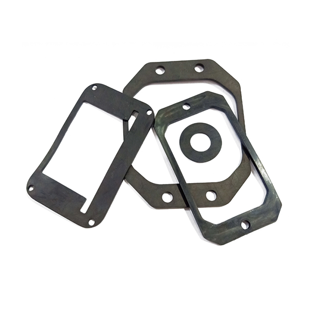
Translating total bolt load into physical geometry requires breaking down mathematical and spatial rules for hole placement. Every dimensional decision impacts the final outcome of the assembly. These dimensions determine whether the elastomer will compress evenly, extrude laterally, or tear under rotational friction.
Bolt Circle Diameter (BCD) positioning affects flange load distribution and gasket compression. Proper bolt hole placement helps minimize flange bending and rotation, ensuring more uniform sealing pressure. The optimal position depends on flange geometry, stiffness, and applicable design standards.
Bolt spacing influences flange rigidity and gasket sealing performance. A spacing of seven times the bolt diameter may serve as a preliminary guideline for certain low-pressure applications, but it is not a universal standard. Excessive spacing can cause flange bowing and uneven gasket compression, increasing leakage risks. Final spacing should be verified through engineering calculations.
Bolt hole clearance must accommodate fastener installation and manufacturing tolerances without creating excessive gaps. Oversized holes can allow rubber gaskets to deform or extrude under compression, potentially causing tearing and leakage. Proper clearance dimensions help maintain accurate alignment, uniform compression, and reliable sealing performance.
Nominal Bolt Diameter | Recommended Clearance Addition | Final Hole Diameter |
|---|---|---|
1/4" to 1/2" | + 1/16" (0.0625") | Bolt Dia + 0.0625" |
5/8" to 1" | + 1/8" (0.125") | Bolt Dia + 0.125" |
1 1/8" and larger | + 1/8" to 3/16" | Bolt Dia + 0.125" to 0.1875" |
This fractional oversizing provides enough tolerance for field technicians to align the mating parts without creating excessive voids that invite lateral material extrusion.
The placement of the bolt hole also dictates the remaining material between the edge of the hole and the gasket's inner or outer diameter. This remaining material is known as the web. Maintaining a minimum web thickness prevents radial tearing.
During installation, the turning of the nut or bolt head generates rotational friction against the flange face. This transfers sheer stress into the elastomer. If the web is too thin, this shear stress rips the rubber from the bolt hole to the outer edge. As a general rule, the minimum edge distance from the center of the bolt hole to the edge of the gasket should be at least 1.5 times the bolt hole diameter. This ensures sufficient cross-sectional area to withstand installation stresses and internal pressure forces.
Moving a sealing solution from a functional prototype to scaled manufacturing requires rigorous documentation standards. Without precise engineering drawings, manufacturers cannot guarantee that the final cut parts will align with the mating flanges. Dimensional drawings must utilize standardized callouts and strict tolerancing frameworks to prevent quality degradation across high-volume production runs.
A 2D CAD drawing for flanged gaskets should clearly specify the Bolt Circle Diameter (BCD), bolt hole quantity, angular spacing or chordal pitch, and hole diameter tolerances. Accurate dimensions ensure proper alignment, fastener clearance, and manufacturing consistency across die-cutting, waterjet, or laser-cutting processes.
Geometric Dimensioning and Tolerancing (GD&T) uses True Position to control bolt hole locations more precisely than traditional ± coordinate tolerances. It defines a circular or cylindrical tolerance zone around each hole's intended position, helping ensure accurate alignment, consistent manufacturing, and reliable gasket assembly.
Gasket drawings should specify the rubber material, Shore A hardness, thickness tolerances, and compression set requirements. These properties directly affect gasket deformation, sealing performance, and resistance to extrusion. Clear material specifications help prevent incorrect substitutions and ensure consistent gasket quality during manufacturing.
Audit your current flange drawings against ASME B16.5 standards to verify that your bolt circle diameters and hole counts match industry specifications.
Calculate the center-to-center bolt spacing on your custom enclosures to confirm they do not exceed the 7x bolt diameter rule.
Update your 2D CAD manufacturing drawings to replace coordinate tolerances with True Position GD&T callouts for all circular bolt patterns.
Partner with a sealing manufacturer who utilizes precision waterjet or die-cutting technology and provides verifiable material certifications.
A: Standard clearance relies on fractional oversizing to allow for stud alignment without creating excessive voids. For bolts under 5/8 inch in diameter, the hole is typically oversized by 1/16 inch. For bolts 5/8 inch and larger, the hole is oversized by 1/8 inch. This prevents the rubber from extruding into the clearance space and tearing against the fastener threads.
A: The Bolt Circle Diameter is the theoretical circle that intersects the exact center of all bolt holes in a circular pattern. Calculate it by measuring the center-to-center distance between two diametrically opposed bolt holes. You must center the BCD perfectly within the flange width to ensure uniform compression and prevent flange rotation.
A: First, calculate the total compressive force required by multiplying the gasket area by the material's Y factor and factoring in internal operating pressure. Then, divide this total required force by the safe load capacity of a single selected bolt. This provides the minimum number of fasteners needed to maintain the seal.
A: Full-face gaskets cover the entire flange surface from the inner to the outer diameter, requiring holes for the bolts to pass through. This design cushions the entire flange, preventing bending moments in brittle materials like cast iron. Ring gaskets sit entirely inside the bolt circle on raised-face flanges, relying on the bolts only for external centering.
A: For low-pressure applications, industry standards dictate the 7x Bolt Diameter rule. The center-to-center spacing between adjacent bolts should not exceed seven times the nominal diameter of the bolts used. Exceeding this distance causes the flange to bow between fasteners, resulting in a localized loss of compressive sealing pressure.
A: The M and Y factors for elastomers are significantly lower than those for rigid metal seals. Because rubber requires less total compressive force to flow into flange imperfections, the total required bolt load is lower. This allows for fewer total bolts or wider bolt spacing compared to spiral wound gaskets.
A: While slotted holes can accommodate difficult alignments or mating parts with differing bolt circles, they are generally discouraged. Slotted holes remove excessive web material and create large, irregular voids. Under compressive load, the rubber will rapidly extrude into the slot, leading to uneven loading, micro-tearing, and eventual blowout.


