
Views: 0 Author: Site Editor Publish Time: 2026-08-24 Origin: Site


Seal failure in industrial and mechanical applications carries exceptionally high stakes. Most blowouts and leaks stem from basic miscalculations in gland geometry rather than defective rubber. When engineered correctly, an elastomeric seal reliably holds thousands of PSI. The core challenge is achieving a zero-clearance barrier without inducing premature material fatigue, excessive friction, or extrusion. You have to balance squeeze and stretch to maintain long-term elastomeric memory. This O-Ring design,compression guide provides the exact parameters needed to master seal design for static and dynamic systems. We will cover how to calculate cross-sectional reduction, manage thermal effects, and optimize gland dimensions to prevent catastrophic leaks on the shop floor.

Optimal Compression Thresholds: Standard O-ring compression should typically fall between 15% and 30% for static seals, with dynamic seals requiring lower compression to minimize friction and excessive wear.
The Stretch Limit: Inside diameter (ID) stretch must generally be maintained between 1% and 5%; exceeding this threshold drastically reduces the cross-sectional area and compromises the seal.
Cross-Sectional Reduction: Stretching an elastomer inherently reduces its cross-section, directly impacting the actual compression achieved within the gland—a critical variable often missed in basic O-ring design.
Directional Pressure Dynamics: In face (flange) seals, the direction of system pressure dictates whether the O-ring should be stretched against the inner or outer diameter of the groove.
Thermal Considerations (Gough-Joule Effect): Stretched elastomers contract when heated, requiring precise calculation of operating temperatures to prevent catastrophic loss of sealing force in rotary applications.
Table of Contents
The primary goal of any installation is creating sufficient initial sealing force. We call this initial force the squeeze. System pressure then amplifies this baseline squeeze during operation. The fluid or gas pushes the elastomer against the gland walls, deforming the rubber into the microscopic machining grooves of the metal hardware. This action blocks fluid or gas bypass entirely, resulting in a true zero-clearance condition. Achieving this requires precise dimensional control over the groove depth, width, and diametral clearance. If the initial squeeze is too low, low-pressure leaks occur before the system pressure can activate the seal. If the squeeze is too high, the material degrades rapidly, taking a permanent set and failing prematurely.
Compression refers to the physical deformation of the cross-section between the mating surfaces of the hardware gland. Squeezing the elastomer creates a physical barrier against fluid flow and maintains the material's elastomeric memory. The rubber constantly pushes back against the metal surfaces. This push-back force is what actually seals the joint. Over time, the material must retain this memory to function. Proper compression calculations ensure the seal lasts through thousands of pressure cycles. When you compress a standard 0.139-inch cross-section by 20%, you are physically flattening it by roughly 0.028 inches. That displaced rubber has to go somewhere, which dictates the required groove width.
To calculate compression mathematically, you use a straightforward formula. You subtract the gland depth from the cross-section, divide that number by the cross-section, and multiply by 100. This gives you the compression percentage. You must run this calculation for both the maximum and minimum material conditions based on your machining tolerances. A seal might show 20% compression at nominal dimensions, but drop to 12% at the maximum tolerance stack-up.
Stretch is the elongation of the inside diameter (ID). You stretch the seal to fit securely over a shaft or within a groove. The ID must intentionally be smaller than the mating hardware to ensure a tight, secure fit. A loose seal can roll, twist, or spiral during assembly. Spiraling causes immediate leak paths and destroys the elastomer. Proper stretch keeps the seal seated flat against the groove wall. However, excessive stretch introduces severe mechanical complications. When you pull a rubber band, it gets thinner. The exact same physics apply here.
The formula for stretch is equally important. You subtract the O-ring ID from the groove diameter, divide by the O-ring ID, and multiply by 100. Just like compression, you must calculate stretch across the full tolerance range of your machined parts. A tight tolerance on the metal groove prevents the stretch percentage from swinging wildly from part to part on the assembly line.
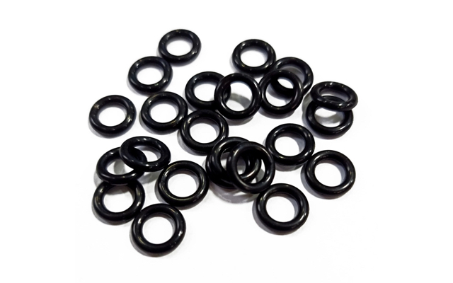
Static seals feature no movement between the mating hardware surfaces. We typically apply a 15% to 30% compression rule for these applications. Static seals divide into radial and axial categories. Radial seals compress between a piston and a cylinder bore. Axial seals, or face seals, compress between two flat flanges. Internal versus external system pressure dictates axial groove design. For internal pressure, seat the O-ring against the outside diameter of the groove. For external pressure, stretch the O-ring against the inside diameter.
Dynamic seals involve moving hardware, such as reciprocating pistons or rotating shafts. These applications require significantly lower compression. We target 8% to 16% squeeze for dynamic systems. Lower compression balances the required sealing force against friction. High friction generates excessive heat and causes abrasive wear. Reducing the squeeze extends the seal's lifecycle while maintaining fluid containment. Rotary applications often require even lower compression targets to survive the constant surface velocity.
Application Type | Recommended Compression Range | Primary Engineering Concerns | Typical Maximum Gland Fill |
|---|---|---|---|
Static (Radial - Piston/Rod) | 15% - 30% | Maintaining elastomeric memory, preventing extrusion | 85% - 90% |
Static (Axial/Face - Internal Pressure) | 15% - 30% | Seating against OD, flange bowing, bolt stretch | 85% - 90% |
Static (Axial/Face - External Pressure) | 15% - 30% | Seating against ID, vacuum sealing | 85% - 90% |
Dynamic (Reciprocating Hydraulic) | 8% - 16% | Friction, heat generation, abrasive wear, spiral failure | 85% - 90% |
Dynamic (Reciprocating Pneumatic) | 8% - 12% | Lack of lubrication, stiction, low-pressure sealing | 85% - 90% |
Dynamic (Rotary Shaft) | 5% - 10% | Gough-Joule effect, high frictional heat, carbonization | 85% - 90% |
Standard compression becomes insufficient at extreme pressures. Systems operating above 1,500 PSI push elastomers to their physical limits. High pressure forces the rubber into the clearance gap between metal parts. This phenomenon is known as extrusion. Once extruded, the rubber nibbles and tears away with every pressure cycle. To prevent this, we integrate backup rings into the gland design. Backup rings sit behind the O-ring on the low-pressure side. They block the clearance gap and keep the elastomer contained.
Selecting the right backup ring material depends heavily on the operating pressure and temperature. Common configurations include:
PTFE (Teflon): Offers excellent chemical resistance and low friction. Ideal for dynamic applications but can cold-flow at extreme temperatures.
Hard Nitrile (90 Durometer): A cost-effective solution for standard hydraulic systems operating up to 3,000 PSI.
PEEK: Used for extreme high-pressure and high-temperature environments where PTFE would fail structurally.
Nylon: Provides a solid middle ground for high-pressure hydraulics requiring tough, extrusion-resistant barriers.
Under-compression presents severe leakage risks. When sealing force drops below system pressure, bypass occurs. This often happens in low-temperature environments where elastomers naturally shrink. Shrinkage reduces the effective squeeze, leading to intermittent or continuous leaks. You must calculate minimum compression at the lowest expected operating temperature. If a machine sits outside in freezing weather, the rubber will contract. If your nominal compression was only 10%, that cold shrinkage might drop the actual squeeze to 2%, resulting in a massive fluid dump upon startup.
Over-compression introduces a different set of mechanical failures. Excessive squeeze accelerates compression set. Compression set is the permanent loss of elastomeric memory. The rubber flattens out and stops pushing back against the hardware. Over-compression also accelerates chemical degradation and physical extrusion. The material experiences higher internal stress, making it vulnerable to environmental attack. Balancing these two extremes is the core of seal engineering. You want enough squeeze to handle the cold, but not so much that you destroy the polymer chains at high temperatures.
Industry standards mandate strict parameters for allowable stretch. The inside diameter should generally stretch between 1% and 5%. Targeting a 2% to 3% stretch is the safest engineering practice. This range ensures a tight fit without over-stressing the polymer chains. Stretching beyond 5% weakens the material structurally. It also accelerates aging and ozone cracking in certain elastomers like NBR and EPDM. Maintaining moderate stretch guarantees the seal stays seated without degrading prematurely.
In some rare cases, engineers might push stretch to 7% or 8% for very small diameter seals where standard sizes don't fit the shaft perfectly. However, doing so requires a complete recalculation of the gland depth to account for the severe cross-sectional reduction. If you ignore this step, the seal will fail.
Elastomers operate under the principle of volume constancy. They behave like incompressible fluids. When you stretch the inside diameter, the cross-sectional diameter must decrease. The total volume of the rubber remains exactly the same. A 5% increase in the inside diameter results in a measurable cross-section decrease.
Failing to account for this reduction creates severe implementation risks. If the cross-section shrinks, the actual compression in the gland drops. You might calculate a 20% squeeze on paper based on the nominal cross-section. However, after stretching the seal 4%, the real squeeze might only be 14%. This lower-than-calculated compression results in unexpected leaks. You must use reduced cross-section values when finalizing gland depths.
ID Stretch Percentage | Approximate Cross-Section Reduction | Impact on Gland Design |
|---|---|---|
1% | 0.5% | Negligible. Standard gland depths apply. |
2% | 1.0% | Minimal. Safe for most standard tolerances. |
3% | 1.5% | Borderline. Verify minimum compression at low temps. |
4% | 2.0% | Significant. Must reduce gland depth to maintain squeeze. |
5% | 2.5% | Critical. Recalculate all compression values using reduced CS. |
The Gough-Joule effect describes a counter-intuitive thermodynamic property of rubber. Stretched elastomers under tension attempt to shrink when exposed to heat. Most materials expand when heated, but stretched rubber contracts. This creates massive problems in high-temperature rotary applications.
Excessive stretch combined with heat causes the O-ring to shrink tightly. It grips the rotating shaft with increasing force. This tighter grip generates more frictional heat. The compounding heat causes rapid material carbonization and catastrophic failure. To mitigate this, we design rotary seals with minimal stretch. Sometimes, we even design the seal to be slightly larger than the shaft, relying entirely on the gland to compress the seal onto the rotating surface. This eliminates the tension and prevents the Gough-Joule effect from destroying the joint.
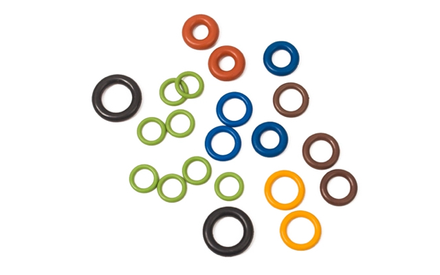
The Shore A hardness of an elastomer dictates its compressive resistance. Durometer directly affects the force required to achieve target compression. Harder materials, like 90 Durometer Nitrile or FKM, resist high-pressure extrusion excellently. However, they require significantly more compressive load to seal properly. Pushing a 90 Durometer seal into a 25% compression state requires massive mechanical force.
This creates an engineering trade-off. High compressive loads can deform mating hardware. Thin-walled cylinders, aluminum manifolds, or plastic housings may crack under the pressure. Softer materials, like 70 Durometer, require less force to compress. They conform easily to rougher surface finishes and minor machining defects. Yet, softer materials extrude much faster under high system pressure. You must match the durometer to both the pressure and the hardware strength.
Chemical compatibility alters the volume during operation. Certain fluids cause the elastomer to absorb liquid and swell. For example, standard Nitrile swells significantly when exposed to certain synthetic lubricants or aggressive fuels. Additionally, the Coefficient of Thermal Expansion (CTE) for rubber is high. Rubber expands from heat roughly ten times faster than steel. Both fluid swell and thermal expansion increase the seal's total volume.
To mitigate this risk, you must calculate maximum gland fill. The O-ring should never occupy more than 85% to 90% of the groove volume. This void space accommodates volume expansion safely. If the gland fills to 100%, the expanding rubber has nowhere to go. It will rupture the hardware or extrude violently, leading to catastrophic failure. Always calculate gland fill at the maximum material condition—meaning the largest possible O-ring cross-section inside the smallest possible machined groove.
The structural requirements of the groove dictate seal success. Surface finish is critical for maintaining the barrier. Static seals tolerate slightly rougher finishes, typically 32 to 63 micro-inches Ra. Dynamic seals require highly polished surfaces, often 8 to 16 micro-inches Ra. Rough surfaces abrade dynamic seals rapidly, acting like sandpaper against the rubber. Lead-in chamfers are also mandatory. Chamfers guide the O-ring into the bore without shearing the outer edge. A standard 15 to 20-degree chamfer prevents installation damage. Clearance gaps between mating parts must remain tight to prevent extrusion.
Groove width is just as important as groove depth. The width must accommodate the flattened cross-section of the compressed seal, plus any thermal expansion or fluid swell. If the groove is too narrow, the seal will overfill the gland. If the groove is too wide, the seal can move back and forth under pressure cycling, leading to premature wear and spiral failure.
Installing stretched seals presents practical assembly challenges. Pushing a seal over threads, splines, or sharp edges causes micro-tears. These invisible tears propagate under pressure, causing premature failure. The seal experiences excessive wear before it even sees operation. Twisting the seal during seating also compromises its structural integrity. A twisted seal will attempt to untwist during dynamic cycling, leading to immediate spiral failure.
Mitigation strategies are essential for assembly lines:
Use proper lubrication to reduce installation friction significantly. Match the grease to the elastomer to prevent chemical degradation.
Employ sizing cones or installation bullets to stretch the O-ring safely over threads or splines.
Train technicians to avoid twisting the seal when pushing it into the groove. Use brass or plastic O-ring picks to prevent scratching the metal hardware.
Maintain clean, controlled assembly environments to prevent metal shavings or debris from contaminating the sealing line.
Validating a design requires rigorous testing protocols. Theoretical calculations must be proven in the physical world. Prototyping allows you to verify assembly forces and fitment. Pressure testing at temperature extremes reveals low-temperature shrinkage leaks. It also exposes high-temperature extrusion limits. You cannot rely solely on room-temperature hydrostatic tests.
Inspect the seals for compression set after thermal cycling. Tear down the prototype and measure the cross-section of the used seal against a new one. If the seal remains flattened and fails to rebound, the material or compression target is incorrect. Iterative testing ensures the final production design meets all performance criteria before you scale up manufacturing.
Utilize digital gland calculators to determine exact cross-sectional reduction based on your specific ID stretch.
Consult with a polymer engineer to select appropriate durometers and backup rings for high-pressure applications.
Design your hardware with a maximum 90% gland fill to safely accommodate thermal expansion and chemical swell.
Implement mandatory lead-in chamfers and specify proper surface finishes on all mating hardware drawings.
Request material samples and conduct physical prototype testing under extreme thermal cycling before finalizing production.
For applications requiring dependable sealing performance, choosing the right O-Ring material, dimensions, and compression parameters is just as important as proper gland design. Cixi Lixu Rubber Products Co., Ltd specializes in rubber sealing products and O-Ring solutions, supporting customers with sealing options for a wide range of industrial and mechanical applications.
A: The maximum allowable stretch for standard applications is generally 5%. An O-ring's inside diameter must be slightly smaller than the hardware for a tight fit. Exceeding 5% stretch over-stresses the polymer chains, accelerates ozone cracking, and drastically reduces the cross-sectional area, which compromises the seal.
A: Stretch directly reduces O-ring compression due to volume constancy. When the inside diameter elongates, the cross-sectional diameter shrinks to maintain the same total volume. This reduction in cross-section lowers the actual squeeze achieved within the gland, potentially causing unexpected leaks if not calculated properly.
A: Standard compression for static O-rings ranges from 15% to 30%. This applies to both radial (piston/rod) and axial (face/flange) seals. The exact target depends on the elastomer's durometer, system pressure, and expected temperature fluctuations, ensuring sufficient elastomeric memory without causing extrusion.
A: Excessive squeeze causes O-rings to fail through compression set, which is the permanent loss of elasticity. The over-compressed rubber flattens and stops pushing back against the hardware. It also leads to accelerated chemical degradation, excessive wear, and physical extrusion into clearance gaps.
A: The Gough-Joule effect is a thermodynamic property where stretched elastomers contract when heated. In rotary seal designs, this causes a stretched O-ring to shrink and grip a spinning shaft tighter as it heats up. This generates excessive friction, leading to rapid material carbonization and failure.
A: The maximum acceptable gland fill is typically 85% to 90%. This leaves 10% to 15% void space within the groove. The empty space safely accommodates volume expansion caused by thermal heat and chemical fluid swell, preventing the expanding rubber from rupturing the hardware.
A: Backup rings should be used in high-pressure applications, typically exceeding 1,500 PSI. Standard compression cannot prevent the elastomer from extruding into clearance gaps at these pressures. Backup rings sit on the low-pressure side of the gland to block the gap and contain the O-ring.


