
Views: 0 Author: Site Editor Publish Time: 2026-07-29 Origin: Site


Specifying a seal based solely on nominal dimensions presents a risky engineering gamble. It often leads directly to catastrophic failure. You might experience gland extrusion or face frustrating assembly issues on the production line. Standard dimensional charts offer a helpful starting point. However, they rarely account for the physical realities of tolerance stacking and elastomer material shrinkage. Ignoring these microscopic variances creates macro-level hardware problems. These issues easily disrupt manufacturing workflows and compromise field reliability.
We designed this guide to equip engineers and procurement teams with an evidence-based evaluation framework. You will learn how to accurately calculate tolerance stacking and mitigate hidden risks in groove design. We explore the critical differences between international sizing systems. This practical knowledge helps you bridge the gap between theoretical specifications and real-world manufacturing constraints. Ultimately, you will ensure optimal supplier selection and achieve long-term component reliability.

Standards dictate availability, not just size: Choosing between AS568, Metric, and JIS impacts supply chain lead times and tooling costs.
Tolerance stacking is unavoidable: Cross-section (CS) and inner diameter (ID) variances must be actively calculated against hardware gland dimensions.
Material dictates final dimensions: Elastomer shrinkage rates mean identical molds produce different final sizes depending on the compound used.
Custom isn't always cost-prohibitive: Non-standard O-rings may offer lower total cost of ownership (TCO) if they eliminate complex hardware machining requirements.
Standard dimensional charts serve as helpful reference tools rather than absolute guarantees. Engineering teams frequently mistake published nominal sizes for exact physical measurements. This assumption creates a dangerous disconnect between theoretical design and actual hardware assembly. Elastomeric parts undergo complex chemical changes during vulcanization. They expand and contract based on temperature, pressure, and tooling variables. Relying strictly on nominal values ignores these dynamic manufacturing variations.
Ignoring the permitted plus-or-minus tolerance ranges on a seal leads to highly predictable hardware failures. We categorize these failures into two main groups based on cross-section (CS) and inner diameter (ID) deviations.
Under-sizing (ID/CS): When a seal falls on the extreme negative end of its tolerance band, it provides inadequate squeeze. Insufficient compression prevents the elastomer from blocking the leak path. This results in immediate low-pressure fluid bypass. In dynamic applications, an undersized seal cannot compensate for normal hardware wear.
Over-sizing (CS): When a cross-section runs on the maximum positive tolerance limit, it causes excessive gland fill. The rubber needs room to expand as temperatures rise. If the groove lacks adequate void space, the seal extrudes into the hardware clearance gap. Over-sized cross-sections also suffer from installation damage, known as nibbling, and they face premature compression set due to extreme stress.
Verifying actual dimensions against specified tolerances requires specialized equipment. You cannot accurately measure soft rubber components using standard metal calipers. The localized pressure from caliper jaws compresses the elastomer. This slight deformation guarantees an inaccurately small reading. To prove dimensional conformity, industry professionals rely on non-contact measurement tools. Optical comparators utilize light and lenses to project an exact shadow of the seal. Conical gauges precisely measure the inner diameter without stretching the component. These advanced methods form the industry standard for verifying true dimensional accuracy.
Selecting the correct standard framework dictates your sourcing strategy, tooling availability, and global hardware compatibility. Engineers must evaluate standard frameworks based on where the equipment will be manufactured and serviced.
The Society of Automotive Engineers (SAE) developed the AS568 specification. It remains the dominant sizing framework across North America. This standard defines sizes using dash numbers rather than direct measurements. It features standardized cross-sections including 0.070", 0.103", 0.139", 0.210", and 0.275". The standard also outlines specific acceptable ID tolerances for each size class. Specifying an AS568 O-Ring makes perfect sense for North American OEM compatibility. It guarantees rapid access to commercial off-the-shelf (COTS) components through almost any regional supplier.
Modern engineering reflects a massive global shift toward metric assemblies. International organizations define these specifications through ISO 3601 and DIN 3771. ISO 3601 strictly categorizes acceptable tolerances into two distinct classes. Class A provides tight tolerances intended for high-precision aerospace or critical industrial applications. Class B offers wider tolerances suitable for general fluid power systems. ISO 3601 also defines strict limits for allowable surface defects. Choosing a Metric O-Ring is absolutely essential for European hardware integration. It supports highly regulated international applications where metric hardware machining is standard.
The Japanese Industrial Standard organizes seals into highly specific operational categories. Instead of generic dash numbers, JIS B2401 uses application-based prefixes. The P-series caters specifically to dynamic or moving applications. The G-series designates seals for static or fixed installations. The V-series accommodates specialized vacuum environments. You must specify a JIS compliant seal when servicing Japanese-manufactured automotive equipment. They also remain mandatory for integrating components into heavy machinery, pneumatic tools, and complex hydraulic systems originating from Japan.

Hardware design must accommodate the worst-case scenario for any given elastomeric component. Engineers achieve reliable sealing only when they mathematically account for tolerance extremes within the hardware groove.
Squeeze represents the percentage of compression applied to the cross-section. Dynamic applications typically require a lower squeeze range, usually between 10% and 15%. This minimizes friction and prevents excessive wear during movement. Static applications demand a higher squeeze, typically ranging from 15% to 30%, to maintain a robust fluid barrier.
You must also carefully calculate the installation stretch. Inner diameter tolerances directly impact how much the seal stretches over the hardware shaft. Industry best practices recommend keeping maximum installed stretch below 5%. Stretching an elastomer causes its cross-section to thin out. This thinning reduces your effective squeeze and compromises the overall seal integrity.
Elastomers act like highly viscous incompressible fluids. When you compress them in one direction, they expand in another. You must design the hardware groove to comfortably accommodate the maximum possible material volume. Calculate your gland fill using the maximum positive cross-section tolerance. You must also factor in the maximum thermal expansion based on your operating temperatures. A properly engineered groove targets a maximum gland fill of less than 90%. Leaving at least 10% void space ensures the material can safely expand without fracturing the surrounding metal or destroying the seal.
Different rubber compounds experience vastly different shrinkage rates during the curing process. Molds are cut from steel to exact dimensions. However, the rubber parts pulled from those molds shrink as they cool. Standard NBR (Nitrile) shrinks predictably. If you switch the material to FKM (Viton) or Silicone, the final cured dimensions will change. Silicone possesses a significantly higher mold shrinkage rate than NBR. Identical tooling will produce noticeably smaller silicone parts. You must verify these material-specific shrinkage rates with your supplier before finalizing your hardware design.
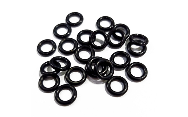
Deciding between a catalog component and a custom-molded solution requires careful technical evaluation. Each approach carries distinct engineering advantages and financial implications.
Evaluation Criteria | Standard / Off-The-Shelf | Custom / Non-Standard |
|---|---|---|
Tooling Investment | Zero. Molds already exist globally. | Requires upfront investment for new steel molds. |
Lead Times | Often immediate or very short. | Longer initial lead times for prototyping and tool cutting. |
Hardware Compatibility | Requires standard groove machining. | Adapts to unique or proprietary hardware constraints. |
Best Use Case | High-volume, rapid prototyping. | Retrofitting legacy systems, space-constrained designs. |
You should prioritize standard catalog sizes whenever your project parameters align with established aerospace or metric tables. Catalog components dramatically accelerate rapid prototyping phases. They make perfect sense for high-volume, standard-margin assemblies where supply chain redundancy remains crucial. Using standard sizes allows procurement teams to source replacements from multiple global vendors without tooling delays.
Custom dimensions become necessary when rigid hardware constraints make standard groove machining impossible. Engineers often encounter exceptionally tight clearance requirements in modern medical devices or aerospace valves. You will also find custom sizes crucial when retrofitting legacy equipment. Older hardware might suffer from internal wear or utilize discontinued sizing systems. Forcing a standard seal into these environments often causes micro-leaks. A custom-molded dimension bridges the gap and restores perfect system integrity.
Do not dismiss custom sizes purely based on upfront tooling costs. You must weigh the Non-Recurring Engineering (NRE) investment against subsequent manufacturing benefits. A custom mold might cost a few thousand dollars initially. However, a custom seal might completely eliminate the need for secondary hardware machining. It can simplify the assembly process and significantly reduce warranty claims associated with fluid leaks. Analyzing these long-term financial impacts often reveals that customized sealing components are highly economical for specialized assemblies.
Sourcing reliable elastomeric components requires more than comparing unit prices. A capable manufacturing partner actively protects your engineering designs through rigorous validation processes.
Look for suppliers who employ advanced automated defect inspection systems. Manual visual inspections simply cannot catch micro-tears or subtle parting line deviations consistently. Your chosen supplier should provide batch-specific dimensional reports upon request. These reports prove the manufactured lots fall accurately within the designated standard tolerances. Robust internal quality protocols prevent defective parts from ever reaching your assembly floor.
Modern industrial applications demand strict material traceability. Evaluate your partner's ability to execute a full Production Part Approval Process (PPAP). This level of documentation verifies manufacturing stability. For specialized industries, verify their material certifications immediately. Medical and food-grade applications require documented compliance with FDA, NSF, or USP Class VI standards. A secure, transparent supply chain guarantees the raw compounds used in production exactly match your engineering specifications.
Avoid simply emailing a list of raw dimensional sizes to potential vendors. You will achieve far better results by sharing your actual hardware prints. Provide comprehensive environmental parameters, including continuous temperatures, peak pressure spikes, and specific chemical media exposures. Direct collaboration with supplier application engineers allows them to recommend appropriate tolerances and compounds. They can spot potential extrusion risks long before you finalize your metal hardware.
Achieving reliable performance demands a careful balance between sizing standards, proactive tolerance management, and intelligent groove design. Standard charts provide an essential foundation, but they do not guarantee real-world performance without rigorous engineering oversight.
Calculate tolerance stacking aggressively to prevent undersized leakage and oversized extrusion.
Understand the differences between aerospace, metric, and Japanese sizing frameworks to streamline global supply chains.
Remember that changing rubber compounds inevitably alters final dimensions due to varying mold shrinkage rates.
Treat elastomeric sealing as a highly integrated system-level engineering task, rather than a localized commodity purchase.
You must actively manage these variables to protect your equipment. Contact your dedicated engineering support team for comprehensive groove design reviews. Request certified standard tolerance charts for your internal reference, and collaborate early on custom tooling quotes to optimize your next critical assembly.
A: Standard charts display nominal dimensions and acceptable tolerance ranges. Real parts vary within these defined plus-or-minus limits. Furthermore, measuring soft elastomers with standard metal calipers deforms the rubber, yielding artificially small readings. You must use optical comparators or conical gauges to verify true dimensions without compressing the part.
A: Generally, no. While "close enough" sizing might survive briefly in low-pressure static environments, the mismatched cross-section tolerance stack proves dangerous. This mismatch usually causes catastrophic failure in dynamic or high-pressure applications. You must independently verify actual hardware dimensions against the component's maximum material condition.
A: Elastomers possess a high Coefficient of Thermal Expansion (CTE). As temperatures rise, rubber components expand significantly faster than surrounding steel or aluminum hardware. Your groove design must include adequate void space. This calculated clearance allows the seal to expand safely without extruding into hardware gaps or damaging the material.
A: ISO 3601 establishes two distinct quality grades. Class A represents much tighter dimensional tolerances. Engineers specify Class A for precision aerospace components and specialized industrial applications requiring strict clearance control. Class B features standard, wider tolerances perfectly suited for general industrial fluid power systems and standard manufacturing assemblies.


