
Views: 0 Author: Site Editor Publish Time: 2026-07-23 Origin: Site


Seal failure drives massive operational and financial losses across industrial applications. Micro-variations in O-ring sizing routinely cause catastrophic leaks, and system downtime quickly follows. Engineers face complex dimensional tolerances, specific gland designs, and unpredictable material behaviors when designing fluid power systems. Relying on guesswork or trial-and-error procurement is a fast track to mechanical failure and blown out seals.
You need a verified, repeatable framework to specify the exact seal required for your hardware. The AS568 standard provides this baseline reliability, eliminating ambiguity across both static and dynamic applications. By referencing a comprehensive AS568 O-Ring,sizing guide, you ensure consistent performance and proper gland fill. This approach standardizes hardware design, streamlines procurement globally, and guarantees that the replacement parts you order will actually fit the machined grooves on your shop floor.
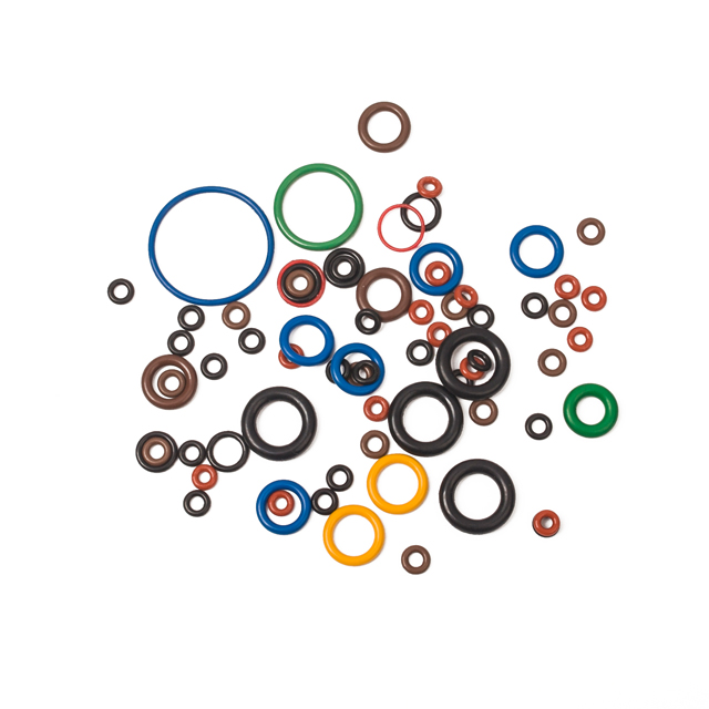
The AS568 standard defines 369 specific O-ring sizes using a unique "dash number" system, ranging from an Inside Diameter (ID) of 0.029 inches up to 26 inches, ensuring global consistency.
Accurate AS568 O-ring selection requires calculating gland fill, installation stretch, and cross-sectional squeeze—not merely matching physical dimensions to a chart.
The standard 2-step sizing workflow involves first matching the measured cross-section (CS) to its standard family, then identifying the closest ID within that family.
Specifying standard AS568 sizes drastically reduces procurement lead times, tooling costs, and minimum order quantities compared to custom or non-standard metric alternatives.
Engineers must factor material shrinkage, Parker size cross-references, and thermal expansion into their final AS568 size specification, as different elastomers alter effective tolerances.
Table of Contents
SAE International governs the AS568 standard. It originally established a strict baseline for aerospace reliability, ensuring that hydraulic flight controls would not fail under extreme pressure. Today, it dominates automotive, manufacturing, and industrial fluid power systems. The standard provides uniform dimensions for elastomeric seals, allowing engineers to design hardware with predictable clearances. It removes the risk of sourcing incompatible parts from different global suppliers. When a machinist cuts a groove for a specific dash number, they know exactly how the rubber will behave inside that cavity.
The standard uses a 3-digit dash number to categorize seals. This system groups O-rings into five primary cross-section families. These include the -000, -100, -200, -300, and -400 series. The first digit indicates the cross-section thickness. The subsequent two digits define the Inside Diameter (ID). A -210 O-ring always shares the same cross-section as a -211, but features a slightly smaller ID. This logical grouping helps engineers scale their designs up or down without having to recalculate their squeeze percentages from scratch.
AS568 Series | Nominal Cross-Section (Fractional) | Actual Cross-Section (Decimal Inch) | Typical Application |
|---|---|---|---|
-000 Series | 1/16" | 0.070" | Pneumatics, compact static seals |
-100 Series | 3/32" | 0.103" | Light hydraulics, automotive fuel systems |
-200 Series | 1/8" | 0.139" | General industrial, dynamic cylinder pistons |
-300 Series | 3/16" | 0.210" | Heavy-duty hydraulics, large flanges |
-400 Series | 1/4" | 0.275" | Massive static face seals, heavy equipment |
AS568 covers a massive range of physical parameters. The standard defines exactly 369 standard sizes. These sizes span from a tiny 0.029 inches (0.74 mm) ID up to a massive 26.00 inches (660.4 mm) ID. This broad scope ensures a standard seal exists for almost any conventional hardware cavity. It covers everything from miniature pneumatic valves in medical devices to heavy-duty hydraulic cylinders on earthmoving equipment. If you are designing a new piece of machinery, you can almost certainly find an off-the-shelf size that fits your requirements.
AS568 sizes correspond directly to other major catalog systems. The Parker 2-xxx sizing series is the most common equivalent found in the field. A Parker 2-210 is identical to an AS568-210. This direct cross-referencing allows procurement teams to source parts interchangeably. You can swap suppliers without altering your hardware drawings or issuing new engineering change orders. It creates a highly liquid supply chain for standard seals, ensuring you are never locked into a single manufacturer for a basic elastomeric component.
Engineers must distinguish between nominal and actual dimensions. Fractional nominal dimensions serve as quick references for mechanics and warehouse staff. For example, a 1/8-inch cross-section is nominal. The actual decimal dimension required for precision engineering is 0.139 inches. Using nominal fractions for gland design leads to incorrect squeeze calculations and inevitable leaks. Always use the exact decimal dimensions listed in the standard when programming CNC machines or drafting CAD models.
Every AS568 O-Ring relies on two foundational measurements. The Inside Diameter (ID) determines how the seal fits over a shaft or inside a bore. The Cross-Section (CS) dictates the thickness of the elastomer. Together, they form a critical relationship with the hardware gland. Getting these two numbers right dictates the success of the seal. If the CS is too small, you lose squeeze. If the ID is too small, you overstretch the rubber and thin out the cross-section.
Field measurement requires a systematic approach. Do not just hold a used seal up to a printed chart and guess. Follow this workflow for accurate identification:
Measure the actual cross-section (CS) using a light-touch caliper or micrometer. Match this decimal value to the nearest standard AS568 cross-section family (e.g., 0.139" means you are in the -200 series).
Measure the Inside Diameter (ID). Within that specific CS family, match your reading to the closest standard AS568 ID.
Verify the material compound to ensure you are replacing like-for-like, as different materials handle heat and chemicals differently.
Physical measurement errors ruin seal selection. Elastomers stretch and deform easily. Lay the O-ring flat on a level, unstressed surface. Do not pull or hang the seal while measuring. This prevents elastomer sagging, elongation, or ovality. A distorted seal yields false ID readings, leading you to specify the wrong dash number. When measuring used seals, remember that compression set flattens the cross-section, so you must measure the thickest remaining part of the rubber to estimate the original CS.
Exact dimensions fluctuate during rubber molding. AS568 defines acceptable tolerance ranges for both ID and CS. A larger ID carries a wider acceptable tolerance band. You must account for tolerance stacking in high-pressure systems. If hardware tolerances and O-ring tolerances stack unfavorably, you risk seal extrusion or insufficient squeeze. For example, if your machined groove is at its maximum allowable depth, and your O-ring is at its minimum allowable cross-section, you might drop below the minimum required squeeze for a reliable seal.
Standard calipers often compress the elastomer, skewing readings. Use a light touch if calipers are your only option. Pi tapes work well for measuring the outside diameter of large seals, allowing you to calculate the ID mathematically. Sizing cones provide rapid, accurate ID checks for smaller dash numbers on the shop floor. Non-contact optical comparators offer the highest accuracy for verifying strict AS568 compliance, especially when dealing with critical aerospace or medical applications where a thousandth of an inch matters.
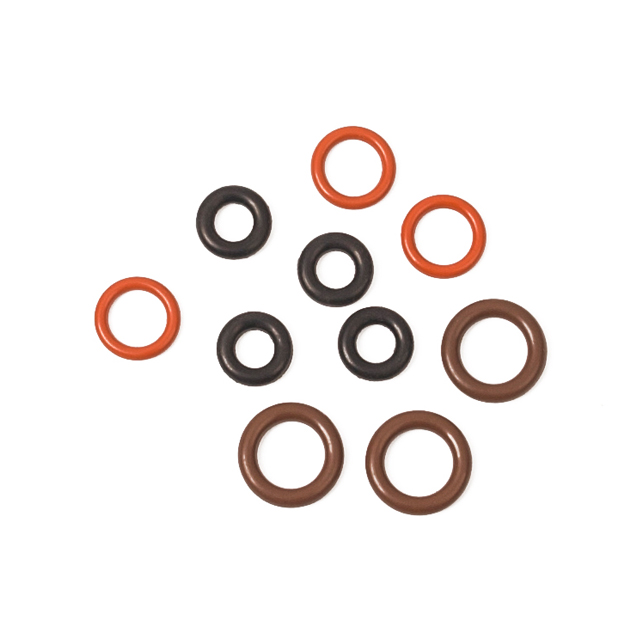
Choose AS568 for immediate availability and global standardization. These seals require lower minimum order quantities because manufacturers stock them by the millions. Hardware tooling for standard dash numbers is universally understood by machinists. If your application allows standard gland dimensions, always specify an AS568 size. It simplifies maintenance and guarantees rapid replacement part sourcing. You can walk into almost any fluid power distributor in North America and walk out with a standard -214 nitrile O-ring.
AS568 falls short in specific scenarios. You need metric sizes when mating with legacy European or Asian equipment built to DIN or JIS standards. Highly constrained hardware envelopes may reject standard cross-sections, forcing you into a custom molded profile. Specialized non-circular groove paths often demand custom shapes. Do not force an AS568 seal into a strictly metric groove. A 3.0mm cross-section groove will not properly compress a 0.103" (-100 series) or a 0.139" (-200 series) O-ring.
Feature | AS568 Standard O-Rings | Metric O-Rings (DIN/JIS) | Custom Molded Profiles |
|---|---|---|---|
Availability | Off-the-shelf, immediate | Readily available globally | Long lead times (weeks/months) |
Tooling Costs | Zero (pre-existing molds) | Zero (pre-existing molds) | High upfront NRE and mold fees |
Hardware Compatibility | Standard inch-based glands | Standard millimeter glands | Proprietary hardware designs |
Minimum Order Quantity | Very low (often single units) | Low to moderate | High volume runs required |
Off-the-shelf AS568 seals eliminate Non-Recurring Engineering (NRE) fees. You avoid expensive custom mold tooling costs entirely. Lead times drop from weeks to days. Custom-molded solutions require upfront investment and longer production cycles. Standard sizes protect project budgets and keep assembly lines moving without waiting for custom rubber curing. When a machine goes down, waiting six weeks for a custom seal is unacceptable. Standardizing on AS568 keeps your maintenance inventory lean and highly reactive.
Procurement teams leverage interactive online size charts to speed up sourcing. You map physical dimensions directly to active part numbers. These digital tools filter by CS family and ID instantly. They connect engineering specifications to in-stock inventory. This digital workflow replaces manual catalog searching and prevents transcription errors. Instead of flipping through a 500-page paper catalog, you input your target ID and CS, and the system outputs the exact dash number and available material compounds.
Cross-sectional compression, or squeeze, creates the seal by forcing the elastomer against the mating hardware surfaces. Static seals typically require 15-30% squeeze. Dynamic seals need less, typically 8-16%. Lower squeeze in dynamic applications minimizes friction, wear, and breakout torque. Calculate squeeze using the maximum groove depth and the minimum O-ring cross-section to ensure contact under worst-case tolerances. If you design for 10% squeeze but tolerance stacking drops it to 2%, the seal will leak at low pressures.
Elastomers act like incompressible fluids. You must keep gland fill below 90%. This void space allows for thermal expansion. It also accommodates chemical volume swell when the rubber reacts to system fluids like hydraulic oil or aggressive solvents. If gland fill reaches 100%, the expanding seal has nowhere to go. It will extrude out of the clearance gap, fracture, and cause catastrophic failure. Always calculate the cross-sectional area of the O-ring against the cross-sectional area of the machined groove.
Keep O-ring stretch between 1% and 5% during installation. Excessive stretch triggers the Gough-Joule effect, where heated elastomers contract instead of expanding. High stretch also reduces the cross-section. This thinning leads to a direct loss of effective squeeze. Never exceed 5% installed stretch unless working with specialized floating seal designs. If you have to stretch an O-ring 10% just to get it over a shaft, you are using the wrong dash number and compromising the seal's integrity before the machine even turns on.
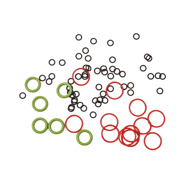
Different elastomer compounds shrink at different rates during molding. Fluorocarbon (FKM) shrinks more than standard Nitrile (NBR). Manufacturers adjust their mold tooling to maintain AS568 dimensional compliance across materials. Always verify that your supplier uses compound-specific tooling. Using a Nitrile mold for a Silicone batch yields undersized, non-compliant seals. If you switch materials to handle a new chemical process, you must ensure the new O-rings still meet the exact AS568 decimal dimensions.
High-temperature environments cause elastomers to expand rapidly. Rubber expands much faster than surrounding metal hardware. This alters the effective squeeze and increases gland fill. As temperatures rise, the rubber softens, increasing the risk of gap extrusion. You must mitigate this by tightening hardware clearances or installing backup rings. A backup ring sits behind the O-ring, blocking the extrusion gap and preventing the softened elastomer from shearing off under high fluid pressure.
Assembly risks destroy perfect seals. Avoid twisting or rolling the O-ring into the groove, which causes spiral failure in dynamic applications. Never shear the elastomer over sharp hardware threads, splines, or unchamfered ports. Implement proper lubrication protocols using fluids compatible with the specific rubber compound. Design hardware with 15-to-20-degree chamfered lead-ins to guide the seal safely into the bore. Clean all surfaces thoroughly to prevent abrasive metal shavings from embedding into the rubber during assembly.
An AS568 O-Ring provides a standardized and reliable sealing solution for a wide range of industrial applications. By selecting the correct dash number, material, and gland design, manufacturers can improve sealing performance, minimize leakage, and ensure long-term equipment reliability.
Choosing a trusted sealing component supplier is equally important for achieving consistent performance. Cixi Lixu specializes in manufacturing high-quality AS568 O-Rings, customized sealing solutions, and precision rubber components for hydraulic, pneumatic, automotive, and industrial applications. With advanced manufacturing capabilities, strict quality control, and extensive industry expertise, the company helps customers achieve dependable sealing performance and long-term operational reliability.
Utilize an interactive AS568 size chart to map your physical measurements to a standard dash number.
Verify your specific gland dimensions against standard engineering formulas to ensure gland fill remains below 90%.
Calculate your worst-case tolerance stacking to guarantee adequate squeeze for your specific static or dynamic application.
Request material test reports (MTRs) from a certified seal supplier to guarantee compound performance and dimensional accuracy.
A: AS568 is an Aerospace Standard published by SAE International. It specifies the exact inside diameters, cross-sections, tolerances, and size identification codes for standard O-rings used in industrial and aerospace applications.
A: Measure the O-ring's cross-section (CS) first to identify the series family. Then measure the inside diameter (ID). Match these two decimal measurements to the corresponding dash number on a standard AS568 chart.
A: AS568 dash numbers match Parker 2-xxx series codes exactly. An AS568-112 O-ring has the exact same dimensions and tolerances as a Parker 2-112 O-ring, allowing for direct interchangeability.
A: AS568 O-rings are defined by specific fractional and decimal inch measurements. Metric O-rings are defined strictly by round millimeter dimensions to fit DIN or JIS hardware.
A: Subtract the hardware gland depth from the O-ring's cross-section. Divide that result by the O-ring's cross-section, then multiply by 100 to get the squeeze percentage.
A: Industry best practice limits installed stretch to 5%. Stretching beyond this thins the cross-section, reduces squeeze, and increases the risk of the Gough-Joule effect in high temperatures.


