
Views: 0 Author: Site Editor Publish Time: 2026-07-23 Origin: Site


Maintaining or manufacturing equipment built to Japanese engineering specifications requires exact dimensional matching. Attempting to substitute standard imperial or ISO metric seals often results in catastrophic failure. Engineers and procurement teams frequently face fluid leaks, pressure drops, and voided warranties. They misidentify a JIS B 2401 seal and attempt to force-fit an AS568 or standard metric equivalent. These substitutes feature incompatible cross-sections that compromise the entire assembly. You cannot simply guess the dimensions when dealing with precision fluid power systems.
This guide breaks down the JIS B 2401 standard. International markets commonly refer to this standard as "Japanese Metrics." We detail the specific operational series, including P, G, S, and V. We also provide a framework for evaluating, designing glands for, and sourcing the correct Japanese standard seal for high-stakes dynamic and static applications. Understanding these specifications ensures your machinery operates safely and efficiently.
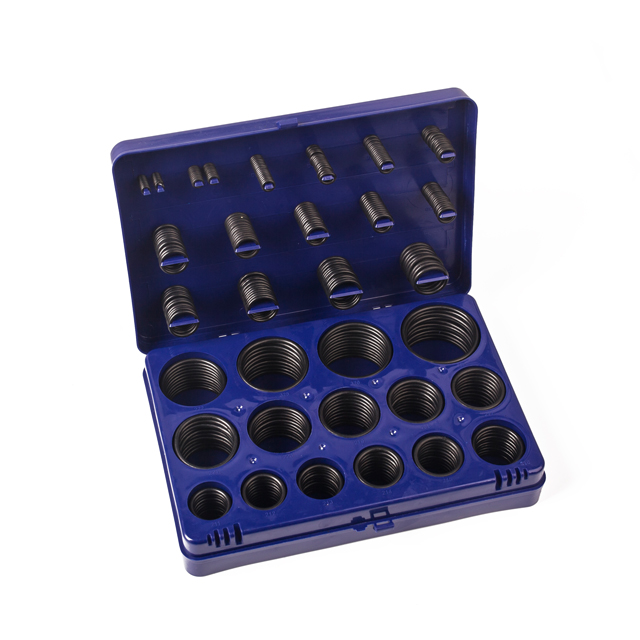
Strict Categorization: The JIS B 2401 standard explicitly divides O-rings into four primary series (P, G, S, and V) based on application type (dynamic vs. static) rather than just dimensions.
Non-Interchangeability: JIS O-rings feature unique cross-sections (e.g., 1.9mm, 2.4mm, 3.1mm) that do not directly cross over to AS568 or standard ISO 3601 metric sizes; substitution invites extrusion or compression set failure.
Gland Design Dependency: Specifying a JIS O-ring requires matching the seal to JIS-specific groove dimensions to ensure optimal squeeze and fill volume.
Supplier Verification: Sourcing reliable Japanese standard seals requires vetting suppliers for strict tolerance controls, batch traceability, and verified material compounding.
Table of Contents
The Japanese Industrial Standards Committee (JISC) governs the JIS B 2401 specification. This governing body establishes rigorous dimensional and material requirements for industrial components. Japanese OEMs like Toyota, Komatsu, and Honda mandate these specific dimensions. They rely on them for hydraulic, pneumatic, and electronic vacuum systems. The strict tolerances prevent fluid bypass under extreme operational stress. When you rebuild a hydraulic pump on a Komatsu excavator, you must use the exact specified components. Deviating from the engineering print guarantees premature failure.
Global distributors frequently catalog these parts as "Japanese Metrics." This industry terminology helps differentiate them from generic European metric seals. A standard European metric seal might have a 2.0mm cross-section. A JIS O-Ring in a similar size category might feature a 1.9mm or 2.4mm cross-section. This slight variance completely changes the compression dynamics within the hardware groove. You will experience immediate leaks if you install a 2.0mm seal in a groove machined for a 2.4mm cross-section.
Engineers working on imported machinery often struggle with these dimensional nuances. They measure an old, deformed seal and assume it matches a standard European metric size. This assumption leads to incorrect ordering and extended equipment downtime. You must consult the original equipment manual or measure the hardware groove directly to determine the correct JIS specification.
The cross-section (CS) and inside diameter (ID) progression logic differs vastly between JIS and AS568. AS568 groups seals by fractional cross-sections and scales the ID incrementally. JIS B 2401 categorizes seals primarily by their intended application. This means a dynamic seal and a static seal with the same ID will have different cross-sections under the JIS standard. This application-first approach ensures the seal geometry matches the physical demands of the operating environment.
Attempting to use a close-match standard metric seal in a JIS-machined groove introduces tolerance stacking. If the substitute seal is slightly too small, you lose compression squeeze. If it is slightly too large, you risk overfilling the gland. JIS B 2401 integrates hardware groove dimensions directly into the standard's documentation. AS568 separates the seal dimensions from recommended gland designs. This integrated approach ensures the seal and the groove function as a single engineered unit.
Tolerance stacking becomes especially problematic in high-pressure hydraulic systems. A standard ISO 3601 seal might fit into the groove, but the extrusion gap might exceed the seal's physical limits. When system pressure spikes, the elastomer extrudes into the gap and shears off. You will find pieces of the seal contaminating the hydraulic fluid, which can destroy downstream valves and pumps.
Standard | Primary Categorization | Cross-Section Logic | Hardware Integration |
|---|---|---|---|
JIS B 2401 | Application Type (Dynamic, Static, Vacuum) | Varies by application series (P, G, S, V) | Groove dimensions integrated into standard |
AS568 | Fractional Cross-Section | Fixed fractional increments (e.g., 1/16", 3/32") | Groove design handled separately |
ISO 3601 | Metric Dimensions | Standardized metric increments | General guidelines provided |
The P series is designed specifically for reciprocating and rotary motion. These applications subject the seal to constant friction and wear. The technical focus here involves heavier cross-sections relative to the inside diameter. The thicker profile withstands dynamic pressure cycling and mechanical abrasion. When a hydraulic cylinder extends and retracts, the P series seal maintains contact with the cylinder wall without rolling or twisting.
You will commonly find P series seals in hydraulic cylinder pistons and pneumatic actuators. They also seal rotating shafts in Japanese heavy machinery and automotive drivetrains. The robust design ensures longevity even when exposed to continuous movement and varying fluid pressures. Mechanics rebuilding Japanese transmissions rely heavily on P series seals to maintain internal fluid pressures.
Installing a P series seal requires proper lubrication. You must coat the seal and the hardware with a compatible assembly fluid before installation. Dry installation causes immediate surface damage to the elastomer. This damage creates micro-leaks that worsen over time as the cylinder cycles.
Engineered for continuous reciprocating motion.
Features thicker cross-sections for wear resistance.
Ideal for hydraulic cylinders and pneumatic actuators.
Handles dynamic pressure cycling effectively.
Requires compatible assembly lubrication during installation.

The G series is engineered for stationary sealing. In these applications, the O-ring compresses between two mating surfaces that do not move relative to one another. The technical focus shifts to slightly thinner cross-sections compared to the P series for the same ID. This optimizes the static squeeze without requiring extra material for wear allowance. You do not need a thick cross-section if the seal never moves.
Common use cases include flanges, covers, and static hydraulic valves. You also see them heavily used in pipe fittings on Japanese equipment. Because the seal remains stationary, the thinner cross-section provides adequate sealing force while saving space within the assembly. This space-saving design allows engineers to create more compact hydraulic manifolds.
When installing G series seals on a flange, you must torque the bolts evenly. Uneven torque creates high-compression zones and low-compression zones. The seal will eventually blow out of the low-compression zone under pressure. Always follow a star pattern when tightening flange bolts to ensure even compression across the entire seal face.
Engineers utilize the S series when spatial constraints prevent the use of standard P or G series seals. These seals feature smaller cross-sections designed for miniaturized assemblies. Implementing S series seals requires tighter machining tolerances on the hardware to maintain the correct compression ratio. You cannot afford sloppy machining when working with micro-seals.
You will find S series seals in automotive fuel injectors and compact electronics. Precision instrumentation also relies on these compact seals. They deliver reliable performance in micro-environments where traditional seals simply will not fit. Handling these small seals requires care. Using sharp picks or screwdrivers during installation will easily cut the thin elastomer.
Measuring S series seals in the field proves difficult. Standard calipers often compress the soft elastomer, giving a false reading. You should use an optical comparator or a dedicated sizing cone to verify the dimensions of these compact seals before installation.
The V series must prevent gas permeation and maintain seal integrity under negative pressure. Vacuum applications present unique challenges, including outgassing and seal deformation. The technical focus involves specific dimensional ratios and strict material requirements. Standard elastomers often contain plasticizers that vaporize in a vacuum, contaminating the system.
Semiconductor manufacturing equipment heavily utilizes the V series. High-vacuum chambers also depend on these specialized seals. The precise engineering prevents contaminants from entering the vacuum environment, ensuring the integrity of sensitive manufacturing processes. You must handle V series seals with lint-free gloves. Finger oils and dust particles compromise the vacuum seal.
Surface finish on the hardware is critical for V series applications. The metal surfaces must be polished to a near-mirror finish. Any scratches or machining marks provide a leak path for gas molecules. You must inspect the hardware grooves with a magnifying glass before installing a V series seal.
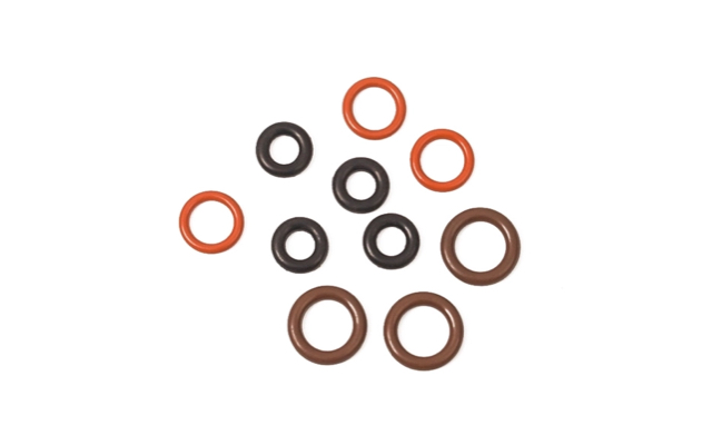
Accurately measuring a JIS O-ring requires precision tools. You must measure the inside diameter (ID) and cross-section (CS) using calibrated calipers or a sizing cone. Never rely on a standard ruler. The JIS B 2401 standard defines acceptable tolerance bands through specific classifications. Class A/Grade G applies to general applications. Class B/Grade F applies to aerospace and precision applications requiring tighter controls.
You must understand the standard's dimensional tables to verify physical tolerances before installation. Historical "Table 3" standards provide the baseline for these measurements. Verifying these dimensions ensures the seal will perform correctly once installed in the hardware. If you measure a seal and it falls outside the acceptable tolerance band, discard it. Do not attempt to use out-of-spec components in high-pressure systems.
Follow these steps to measure a seal accurately in the field:
Clean the seal thoroughly to remove any oil or debris.
Lay the seal flat on a clean, level surface.
Use digital calipers to measure the cross-section lightly without compressing the rubber.
Measure the inside diameter at three different points and calculate the average.
Compare your measurements against a verified JIS B 2401 dimensional chart.
Matching the JIS seal to the correct groove width, depth, and surface finish is critical. You must achieve the required 15-30% compression squeeze. The surface finish, measured in Ra values, dictates how well the seal mates with the hardware. You must consult a JIS-specific O-ring groove chart for recommended dimensions. Guessing the groove dimensions leads to immediate seal failure.
Dynamic P series grooves differ significantly from static G series hardware dimensions. You must also address extrusion gaps and pressure limits. High-pressure JIS applications often necessitate back-up rings governed by the JIS B 2407 standard. These back-up rings prevent the elastomer from extruding into the clearance gap. You install the back-up ring on the low-pressure side of the seal.
When machining new hardware for a JIS seal, pay close attention to the groove radii. Sharp corners in the groove will cut the seal during installation or under pressure cycling. You must machine smooth radii on all internal and external groove corners according to the standard's specifications.
JIS Series | Application Type | Relative Cross-Section | Primary Use Case |
|---|---|---|---|
P Series | Dynamic / Moving | Thicker / Heavier | Hydraulic pistons, rotary shafts |
G Series | Static / Fixed | Thinner / Lighter | Flanges, static covers, valves |
S Series | Compact / Special | Miniaturized | Fuel injectors, precision instruments |
V Series | Vacuum | Optimized Ratio | Semiconductor equipment, vacuum chambers |
Evaluating elastomers requires understanding the operating environment. You must select materials based on fluid compatibility, temperature ranges, and durometer requirements. Standard JIS specifications commonly utilize NBR, FKM (Viton), EPDM, and Silicone. Each material offers distinct advantages for specific fluids and thermal conditions. Using NBR in a high-temperature synthetic oil application will cause the seal to harden and crack within weeks.
You must also ensure materials meet specific industry compliance standards. RoHS and REACH compliance are mandatory when exporting from or importing to global markets. Verifying these certifications prevents regulatory issues and ensures the materials are safe for their intended applications. Always request material data sheets from your supplier before approving a new seal compound.
Durometer, or hardness, plays a major role in extrusion resistance. A standard 70-durometer seal works well for low-pressure applications. High-pressure hydraulic systems often require 90-durometer seals to resist extrusion into the clearance gap. You must match the material hardness to the system pressure and the hardware extrusion gap.
NBR: Excellent for standard hydraulic oils and pneumatics.
FKM: Superior chemical resistance and high-temperature tolerance.
EPDM: Best for outdoor weathering and steam applications.
Silicone: Ideal for extreme temperature variations and clean environments.
Using non-JIS seals in JIS hardware causes severe mechanical failure modes. Nibbling occurs when the seal extrudes into the clearance gap and gets torn by moving metal parts. Spiral failure happens in dynamic applications when the seal rolls within the groove. Explosive decompression destroys seals in high-pressure gas applications when pressure drops rapidly. These failures are not theoretical; they happen daily on job sites when technicians use incorrect parts.
These failures stem directly from improper cross-section matching. A "will-fit" seal might seem acceptable during assembly. However, under operational pressure and temperature fluctuations, the dimensional mismatch becomes obvious. The resulting downtime and cleanup costs far exceed the effort required to source the correct part. A blown hydraulic seal on an excavator can cost thousands of dollars in lost production and environmental cleanup.
You must train your maintenance staff to recognize the difference between standard metric seals and JIS seals. Provide them with accurate measuring tools and clear dimensional charts. Do not allow them to dig through a generic O-ring kit to find something that "looks close enough."
Auditing a supplier requires strict criteria. You must look for ISO 9001 certification. You should also verify their batch testing protocols and dimensional inspection capabilities. A reliable supplier will maintain comprehensive quality control documentation for every batch of seals they produce. If a supplier cannot provide traceability documentation, you should not buy from them.
You must request and review material test reports (MTRs) and certificates of conformance (CoC). These documents verify compliance with JIS B 2401 material classifications. Look for specific compound classes such as Class 1, Class 2, Class 3, and Class 4. This verification ensures the elastomer performs exactly as specified by the standard. You need proof that the FKM seal you ordered is actually FKM and not a cheap blend.
Visit your supplier's facility if possible. Inspect their storage conditions. Elastomers degrade when exposed to ozone, direct sunlight, and extreme temperatures. A quality supplier stores their seals in climate-controlled, UV-protected environments to ensure maximum shelf life.
The supply chain reality is that JIS O-rings are less commonly stocked in North America and Europe than AS568 sizes. You cannot rely on next-day availability for specialized Japanese metric seals. You must implement strategies to prevent operational downtime caused by missing components. Waiting three weeks for a $2 seal to ship from overseas is unacceptable when a production line is down.
Establishing blanket orders helps secure long-term supply. You should also maintain adequate safety stock for critical sizes. Vendor-managed inventory (VMI) programs shift the burden of stock monitoring to the supplier. These strategies ensure you always have the right seals on hand when maintenance schedules demand them. Work with your procurement team to identify the most frequently used JIS sizes in your facility and build a dedicated inventory.
A JIS O-Ring is essential for maintaining reliable sealing performance in Japanese-engineered equipment. By selecting the correct JIS B 2401 series, material, and groove design, manufacturers can reduce leakage risks, improve equipment reliability, and extend service life.
Choosing a reliable sealing component supplier is equally important for long-term performance. Cixi Lixu specializes in manufacturing high-quality JIS O-Rings, customized sealing solutions, and precision rubber components for a wide range of industrial applications. With advanced production technology, strict quality control, and extensive industry experience, the company helps customers achieve reliable sealing performance across hydraulic, pneumatic, automotive, and industrial equipment.
Take these actionable steps to secure your fluid power systems:
Consult a verified JIS B 2401 size chart to identify your exact required part number.
Measure your existing gland dimensions with precision calipers to confirm the correct series.
Request technical data sheets and material samples from a qualified sealing partner before placing bulk orders.
Establish a safety stock protocol for critical JIS sizes to mitigate supply chain delays.
A: JIS B 2401 is the specific Japanese Industrial Standard document. It governs the dimensions, tolerances, and classifications of O-rings used in Japanese-engineered machinery and fluid power systems.
A: Yes. "Japanese Metrics" is a common industry synonym for JIS B 2401 O-rings. However, they represent a highly specific standard distinct from generic DIN or ISO metric seals.
A: This is highly discouraged. Cross-section mismatches between AS568 and JIS standards lead to improper squeeze, extrusion, and eventual leakage in the hardware groove.
A: The P series is designed for moving or dynamic applications and features thicker cross-sections. The G series is engineered for fixed or static applications with slightly thinner profiles.
A: You must use a JIS-specific groove chart. This chart identifies the recommended gland depth, width, and radius based on your chosen P, G, S, or V series part.
A: Use precision calipers to measure the Inside Diameter (ID) and Cross-Section (CS) in millimeters. Never use a standard ruler, as JIS tolerances require exact precision.
A: They utilize standard industrial elastomers like Nitrile (NBR), Fluorocarbon (FKM), and EPDM. The standard dictates dimensions, while material specifications fall under distinct JIS compound classes.


