
Views: 0 Author: Site Editor Publish Time: 2026-07-23 Origin: Site


A single dimensional error in a low-cost sealing component routinely leads to catastrophic system downtime, severe fluid loss, and massive maintenance overruns. In industrial engineering, the financial impact of a failed machine seal is disproportionately high compared to the cost of the part itself. The core engineering challenge lies in specifying exact seal dimensions within globalized manufacturing environments. Relying on imperial AS568 sizes as substitutes for true metric dimensions creates uneven compression, extrusion risks, and inevitable leakage. This guide serves as a technical evaluation framework for selecting, sizing, and specifying the correct Metric O-Ring. By understanding exact dimensional requirements, international standards, and material properties, engineers can ensure long-term integrity and reliable performance across complex industrial applications.
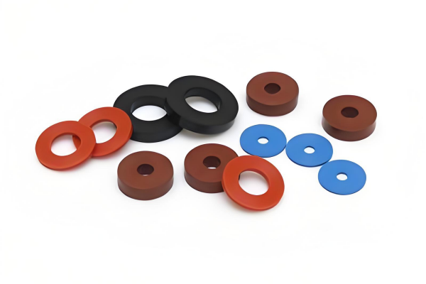
Precision is Non-Negotiable: True metric O-rings are defined by exact Cross-Section (CS) and Inside Diameter (ID) measurements in millimeters; relying on "closest fit" imperial conversions compromises seal integrity.
Standards Dictate Performance: Adherence to international standards (ISO 3601, ISO 6149, DIN 3771) ensures consistency in gland design and hardware tolerances.
Material Matches Environment: Selecting the right elastomer (Nitrile, Viton, PTFE, Silicone) requires evaluating continuous operating temperature, chemical exposure, and system pressure.
Hardware Compatibility: A metric O-ring is only as effective as its corresponding groove dimension; proper gland design prevents extrusion and compression set failures.
Table of Contents
The primary function of a Metric O-Ring is to act as a reliable barrier, blocking the leakage of gases or fluids in mechanical systems. When compressed between two or more surfaces, the elastomer deforms to fill the cavity. This deformation creates a zero-clearance physical barrier that holds back system pressure. The effectiveness of this barrier depends entirely on the initial compression squeeze applied during assembly and the material's ability to maintain that outward force against the mating hardware over time.
Engineers must distinguish between applications where these components serve as static gaskets and where they act as active sealing elements. As static gaskets, they secure pipe joints, tubes, and flange connections where there is no relative motion between the mating surfaces. The hardware simply bolts together, compressing the elastomer into a fixed position. In contrast, active sealing elements operate in dynamic hydraulic and pneumatic components. These seals constantly adjust to pressure fluctuations, mechanical movement, and thermal expansion, requiring a much higher degree of precision in both material selection and hardware machining.
The operational environment dictates the design approach for the machine seal. Field experience shows that applying static design principles to a dynamic application guarantees premature failure.
Static Seals: These applications require axial and radial compression. Examples include heavy-duty flanges, threaded plugs, and high-pressure tube fittings. Because there is no movement, static seals can tolerate higher squeeze percentages (often up to 30%) and harder durometer materials without risking abrasive wear. The primary concern is preventing extrusion under high static pressure.
Dynamic Seals: These involve reciprocating, oscillating, and rotary applications, such as hydraulic cylinder pistons, pneumatic rods, and rotating shafts. Evaluation criteria for dynamic seals must account for friction, heat buildup, and wear resistance. Squeeze percentages are typically kept lower (10% to 15%) to minimize friction, necessitating precise gland tolerances and specialized lubrication to maintain the seal without tearing the elastomer.
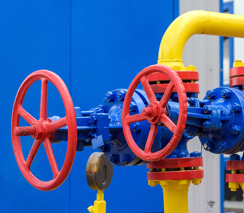
Establishing baseline metrics for success is mandatory for long-term performance. Optimal compression squeeze typically ranges from 10% to 30%, depending heavily on whether the application is static or dynamic. Friction management requires careful material selection and surface finish specifications on the hardware—typically requiring a surface finish of 16 to 32 micro-inches RMS for dynamic surfaces. Finally, long-term dimensional stability ensures the elastomer resists compression set and maintains its sealing force over thousands of operating hours, even under extreme temperature cycling.
Accurate measurement and specification form the foundation of mechanical reliability. A true metric component is designed specifically for metric hardware, and understanding its nomenclature is the first step in proper specification. Guesswork during the measurement phase leads directly to fluid leaks on the factory floor.
The standard nomenclature for a Metric O-Ring is expressed as Inside Diameter (ID) x Cross-Section (CS) in millimeters. For example, a 50.00 x 3.00 designation indicates a 50mm ID and a 3mm CS. Precision is paramount; a 3.00mm cross-section is functionally different from a 3.53mm (AS568 imperial) cross-section.
Accurately measuring these dimensions requires proper tooling and methodology. Follow this sequence to ensure accurate field measurements:
Clean the elastomer thoroughly to remove all hydraulic fluid, grease, and debris.
Use precision digital calipers to measure the cross-section (CS) lightly. Do not compress the rubber with the caliper jaws.
For the inside diameter (ID) of small seals, slide the component down an O-ring sizing cone until it rests naturally without stretching.
For large-diameter IDs, wrap a Pi tape around the inside circumference to get an exact reading.
Verify the measurements against a standard metric size chart to confirm the exact specification.
The critical rule during measurement is to avoid stretching the elastomer. Stretching artificially reduces the cross-section and leads to inaccurate readings, resulting in the procurement of undersized replacement parts.
Standard ordering protocols combine dimensional data with material specifications. A typical industry part number might include the ID, CS, material compound (e.g., NBR, FKM), and Shore A durometer hardness. For instance, "50x3-FKM-75" specifies a 50mm ID, 3mm CS, Viton material, and 75 durometer hardness. Understanding this sequence ensures the exact component is procured for the specific machine seal requirement.
Global manufacturing relies on standardized dimensions to ensure interoperability. Different regions and industries default to specific standards, and mixing them up causes hardware incompatibility.
Standard | Primary Application | Key Characteristics |
|---|---|---|
ISO 3601 | General-purpose metric applications | The global standard detailing quality acceptance criteria, size codes, and dimensional tolerances for fluid power systems. Divided into Class A (precision) and Class B (standard). |
ISO 6149 | Metric Tube Fittings and fluid power ports | Defines 13 specific standard metric sizes that correlate directly to standard metric straight-thread port sizes. Essential for high-pressure hydraulic connections. |
DIN 3771 | Legacy European machinery | Traditional German standard defining elastomer tolerances and quality limits. Still heavily prevalent in older industrial equipment imported from Europe. |
JIS B 2401 | Japanese and Asian equipment | Categorized by functional series: P (Dynamic/Packing), G (Static/Gasket), S (Special/Small), and V (Vacuum). Each series has specific cross-section requirements. |
Substituting AS568 (imperial) sizes for metric hardware introduces severe mechanical risks. An imperial size might appear to fit during bench assembly, but the cross-section will inevitably be slightly too large or too small for the machined metric groove. A cross-section that is too small fails to provide adequate compression squeeze, leading to immediate leakage when the system pressurizes. A cross-section that is too large overfills the gland. This causes uneven compression, spiral failure during dynamic movement, and premature degradation of the machine seal as the rubber is sheared off by the mating hardware.
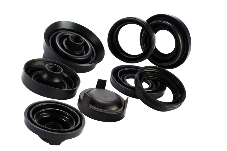
Dimensional accuracy must be paired with the correct elastomer compound. Mapping specific elastomer properties to industrial application outcomes prevents premature chemical degradation and thermal failure. A perfectly sized seal made from the wrong material will fail within hours of operation.
Nitrile (NBR) is the workhorse of the industry for general-purpose hydraulic and pneumatic applications. It offers excellent resistance to petroleum-based oils, fuels, and standard hydraulic fluids, making it ideal for standard industrial machinery operating between -30°C and 100°C. However, Nitrile degrades rapidly under UV exposure, ozone, or extreme weathering, causing it to crack and fail.
EPDM is specified for outdoor applications, UV exposure, and steam environments. It handles polar solvents, brake fluids, and hot water exceptionally well. EPDM is the standard for automotive cooling systems and outdoor weather sealing. However, it will swell massively and fail immediately if exposed to petroleum-based oils or hydrocarbon fuels.
Viton (FKM) is engineered for high-temperature operations and aggressive chemical environments. It maintains its mechanical properties in the presence of aliphatic and aromatic hydrocarbons, concentrated acids, and synthetic lubricants at continuous temperatures up to 200°C. Viton is the default choice for chemical processing plants and high-heat engine applications.
Silicone offers extreme temperature flexibility, remaining pliable in freezing conditions down to -60°C while withstanding high dry heat up to 230°C. It is frequently specified for medical devices and food-grade compliance due to its purity and lack of odor. However, Silicone possesses poor tensile strength and low abrasion resistance, making it entirely unsuitable for dynamic friction applications.
PTFE (Teflon) provides virtually universal chemical resistance and extremely low friction. It can survive environments that destroy all other elastomers. However, PTFE lacks elasticity. It is prone to cold flow and compression set, meaning it will not spring back into shape after being compressed. It requires specialized, split-hardware designs for installation because it cannot be stretched over a shaft.
FEP/PFA encapsulated metric O-rings offer a highly effective hybrid solution. They feature a resilient elastomer core (usually Silicone or Viton) wrapped in a thin, continuous PTFE jacket. This design provides the chemical resistance and low friction of PTFE with the mechanical memory and spring-back of a standard rubber Metric O-Ring. They are highly effective for dynamic seals in harsh chemical environments where standard rubber would degrade.
Selecting the correct Shore A hardness is dictated by operating pressure and hardware extrusion gaps. A standard 70 Durometer material is suitable for lower pressures (up to 1500 PSI) and standard machining clearances. As system pressure increases, the fluid forces the elastomer toward the clearance gap between the metal parts. To resist this extrusion, a harder 90 Durometer material is required. Failing to match hardness to pressure results in catastrophic extrusion failure, where the rubber is literally blown out of the groove.
A Metric O-Ring cannot function independently; its performance is entirely dependent on the machined groove (gland) it occupies. The hardware dictates the success of the seal.
The mathematical relationship between the cross-section and the machined groove depth and width dictates the compression squeeze and volumetric fill. The groove depth determines the exact percentage of squeeze applied to the cross-section. The groove width must accommodate the deformed shape of the compressed elastomer without allowing it to roll, twist, or become trapped during assembly.
Inside diameter stretch must be strictly managed during hardware design. Acceptable limits for ID stretch are typically capped at 5% for most applications. Stretching the elastomer beyond this point reduces its cross-section significantly. This reduction directly lowers the compression squeeze, compromising the machine seal and creating a leak path.
Optimal gland fill is calculated between 75% and 85%. The groove must never be 100% filled by the elastomer. Leaving void space allows for thermal expansion and potential fluid swell. Rubber acts like an incompressible fluid; if the gland is overfilled, thermal expansion will cause the elastomer to rupture the hardware, bend shafts, or extrude violently out of the assembly.
In high-pressure hydraulic applications (exceeding 3000 PSI), the clearance gap between mating metal parts becomes a critical failure point. When fluid pressure exceeds the physical strength of the elastomer, the material is forced into this extrusion gap, nibbling away the edges of the seal. Integrating PTFE back-up rings on the low-pressure side of the groove blocks this gap. The back-up ring acts as a rigid barrier, allowing standard elastomers to operate safely at significantly higher system pressures without extruding.
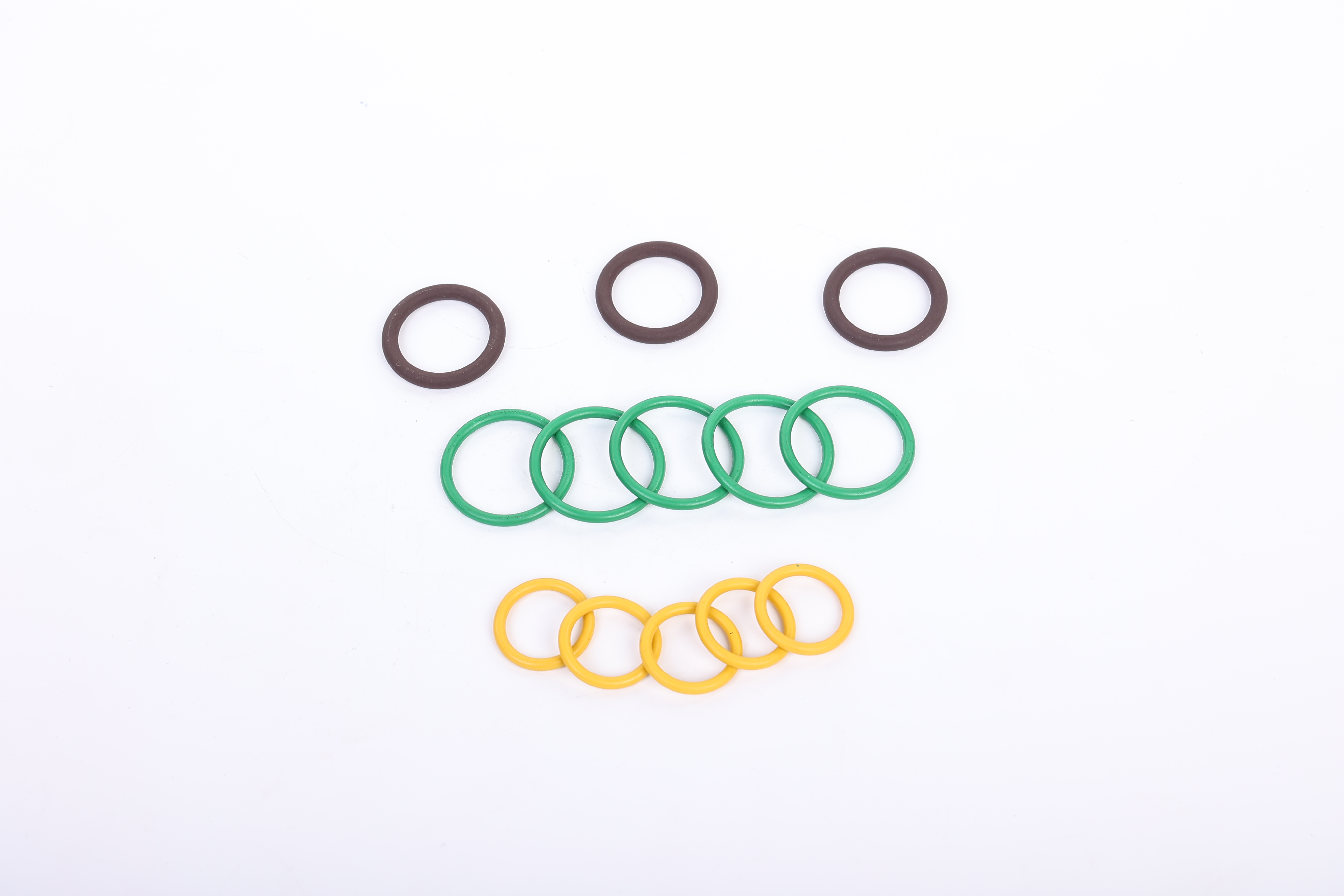
Recognizing the physical signs of failure allows engineers to adjust dimensions, materials, or hardware designs before catastrophic system breakdown occurs on the production floor.
Compression Set: The elastomer loses its elasticity and takes on a flat, permanent deformation matching the shape of the groove. This is caused by excessive operating temperatures, prolonged exposure to incompatible fluids, or selecting a low-quality compound.
Extrusion and Nibbling: The edges of the Metric O-Ring appear chewed, chipped, or frayed. This indicates hardware clearance issues, severe pressure spikes, or a durometer that is too soft for the application's pressure rating.
Abrasion and Spiral Failure: Specific to dynamic applications, the surface shows heavy wear, flat spots, or deep spiral cuts wrapping around the cross-section. This results from poor surface finish on the hardware, lack of lubrication, or excessive stroke speeds causing the seal to roll and twist within the groove rather than sliding smoothly.
Chemical Degradation: The seal appears blistered, cracked, or excessively swollen. This is a direct result of fluid incompatibility, requiring an immediate material change.
Establish strict inspection routines prior to installation. Components must be visually inspected for surface defects, excessive flash lines from the molding process, and dimensional accuracy. During assembly, proper lubrication is mandatory. Installing a dry elastomer over sharp threads, splines, or unchamfered edges will cause shearing, twisting, and immediate failure upon system pressurization. Always use installation sleeves or tape over threads to protect the seal during assembly.
A Metric O-Ring is only as reliable as its dimensions, material selection, and installation quality. By selecting the correct metric size, international standard, elastomer compound, and groove design, engineers can significantly reduce leakage risks, improve sealing performance, and extend the service life of industrial equipment.
Choosing a reliable sealing component supplier is equally important for long-term sealing performance. Cixi Lixu specializes in manufacturing high-quality Metric O-Rings, customized sealing solutions, and precision rubber components for a wide range of industrial applications. With advanced production technology, strict quality control, and extensive industry experience, the company helps customers achieve reliable sealing performance across hydraulic, pneumatic, automotive, and industrial equipment.
Measure exact hardware dimensions using precision digital calipers and Pi tapes to determine the required cross-section and inside diameter without stretching the existing seal.
Identify the required standard (ISO, DIN, or JIS) based on the equipment's origin to ensure the replacement part matches the machined gland tolerances perfectly.
Select the elastomer material based on the specific chemical media, continuous operating temperature, and environmental exposure of the application.
Verify the material durometer against the maximum system pressure and hardware extrusion gaps, integrating PTFE back-up rings if operating above 1500 PSI.
Implement strict pre-installation inspection and lubrication protocols for all maintenance personnel to prevent shearing and twisting during assembly.
A: Use precision digital calipers to measure the cross-section (CS). For the inside diameter (ID), use calipers for small sizes, sizing cones, or Pi tapes for large diameters. Never stretch the elastomer during measurement, as this reduces the cross-section and provides a false reading.
A: No. Imperial substitutions often fail because the cross-section will not match the metric groove depth perfectly. This results in incorrect compression squeeze, volumetric fill mismatch, and improper gland fill tolerances, leading to extrusion or leakage.
A: ISO 6149 defines specific metric sizes designed exclusively for use in Metric Tube Fittings and fluid power ports. It includes 13 distinct sizes that map directly to specific metric straight-thread profiles to ensure reliable high-pressure sealing.
A: Under the Japanese Industrial Standard (JIS B 2401), the 'P' series stands for packing and is engineered for dynamic, moving applications. The 'G' series stands for gasket and is designed with different cross-sections for static, fixed applications.
A: Higher system pressures force the elastomer into hardware clearance gaps. To prevent extrusion, select a harder material, typically 90 Shore A durometer, or integrate PTFE back-up rings into the gland design to block the extrusion path.
A: ISO 3601-1 defines manufacturing tolerances. Class A provides tighter tolerances for precision industrial applications and dynamic seals, while Class B offers standard tolerances suitable for general-purpose static sealing.
A: Flattening is known as compression set. It occurs when the elastomer loses its mechanical memory due to excessive heat, chemical attack, or the selection of a compound with poor elasticity for the required operating environment.


